Mechanical Design Project
Type: Individual
Total Mark: 30% of the total marks available
Design Task
Design a four-bar elevation mechanism for a 120 kg ground-station antenna used to track satellites in low Earth orbit. The mechanism must move the antenna upward from $\alpha_e=160^\circ$ to $\alpha_e=90^\circ$ in 9 seconds. A reversible geared motor and a belt drive must drive the mechanism. You must design the linkage, analyse its motion and loads, and select the motor, belt, output shaft and bearings.
Mechanical Configuration
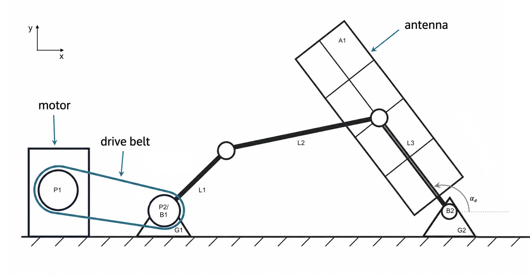
- A planar four-bar mechanism with fixed pivots $G1$ and $G2$, input rocker $L1$, coupler $L2$ and output rocker $L3$
- An antenna frame rigidly attached to and parallel with $L3$
- A reversible geared motor that drives $L1$ through motor pulley $P1$, a single-stage belt drive and input-shaft pulley $P2$
- Pulley $P2$ and $L1$ rigidly connected to the input shaft at $G1$, with the shaft supported by two bearings forming arrangement $B1$
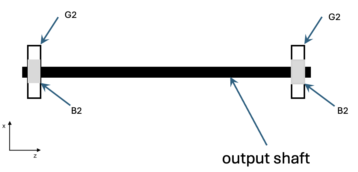
- An output shaft at $G2$, supported by two bearings forming arrangement $B2$ and keyed to $L3$
Bearing arrangement $B1$ is not part of the required calculations or bearing selection.
Design Requirements
Your design must meet all of the following requirements:
- Move the antenna upward from $\alpha_e=160^\circ$ to $\alpha_e=90^\circ$ in 9 seconds.
- Use the antenna angle $\alpha_e$ shown in Figure 1: $\alpha_e=90^\circ$ is vertical and $\alpha_e=160^\circ$ is the starting position.
- Use a trapezoidal motion profile: constant angular acceleration from 0–2 s, constant speed from 2–7 s, and constant angular deceleration from 7–9 s.
- Keep the input-link speed at or below 10 rpm.
- Keep all moving links and joints inside a rectangular area that extends 2.00 m from $G1$ towards $G2$ and 0.80 m above the line $G1G2$. This limit does not apply to the antenna, motor, pulleys, shafts, bearings or supporting structure.
- Ensure that the four links can connect at every required antenna position. The mechanism must move smoothly from start to finish without jumping or changing to a different linkage configuration.
- Select bearings for arrangement $B2$ that meet the required life with 98% reliability.
- Use a minimum design safety factor of 2 for motor torque, belt capacity, brake holding torque and output-shaft strength.
Design Data
| Parameter | Value |
|---|---|
| Antenna mass and dimensions | 120 kg; 2.5 m × 4.7 m |
| Fixed-pivot spacing, $G1G2$ | 1.20 m |
| Wind speed, air density and drag coefficient | 12.9 m/s; 1.225 kg/m³; 1.2 |
| Belt-drive efficiency | 90% |
| Bearing calculation duty | Conservative design speed of 5 rpm for 1 hour per day over 8 years |
Analysis Assumptions
- Model the antenna as a uniform flat plate. Its centre of mass and centre of pressure are on the centreline of $L3$, 0.35 m from the output shaft.
- The 4.7 m dimension is in the plane of motion ($x, y$) and perpendicular to the shaft.
- Assume that gravity, inertia and wind act at the same time. The wind force acts perpendicular to the full antenna area and opposes upward movement.
- The antenna starts and finishes at rest. Neglect jerk and short-duration shock loads when the acceleration changes.
- Neglect the masses of $L1$, $L2$ and $L3$ in the dynamic analysis.
- The two bearings in output-shaft arrangement $B2$ are 0.60 m apart and are placed symmetrically about the antenna centreline. Apply the transverse load from the antenna and $L3$ midway between the bearings. Assume that the radial bearing reactions are equal, and neglect axial load.
- For bearing life, find the largest $B2$ bearing reaction from the dynamic cases at $t=0$ and $8$ s and from all stationary antenna positions between $\alpha_e=160^\circ$ and $90^\circ$. Use the magnitude of this reaction as a constant equivalent radial load.
- For output-shaft design, use the worst case from the dynamic cases at $t=0$ and $8$ s and from all stationary antenna positions between $\alpha_e=160^\circ$ and $90^\circ$. Use the midpoint transverse load to calculate bending. Use the largest absolute antenna torque about $G2$ to calculate torsion.
Clearly state and justify any additional assumptions you make.
Tasks to Complete
1. Mechanism and Kinematics
- Identify all links and joints. Confirm the mechanism mobility using Gruebler’s equation.
- Propose and evaluate at least three combinations of values for $L1$, $L2$ and $L3$.
- For each candidate, find the maximum absolute static holding torque at the input shaft, including gravity and wind, and the maximum input speed. Check that the mechanism remains inside the mechanism envelope, that its links connect at every required position, and that it moves without jumping or changing to a different configuration.
- Choose one feasible candidate from the designs that you evaluated and explain why you prefer it. State which linkage configuration you will use throughout the movement.
- Derive the position-loop equations using your stated coordinate system and angle conventions. Show one complete position calculation at $\alpha_e=125^\circ$.
- For the selected linkage, plot the output-link angle $\alpha_e$, angular velocity and angular acceleration against time over the complete 9-second movement. Plot the corresponding input-link angle, angular velocity and angular acceleration. Clearly mark the values at $t=0$ and $8$ s. Identify the maximum input-link speed.
2. Dynamic Loads and Input Torque
Calculate the antenna weight, wind force and mass moment of inertia about the output shaft at $G2$. Include the effect of the 0.35 m distance between the centre of mass and the output shaft. Calculate the wind force from
\[F_W=\frac{1}{2}\rho C_D A V^2.\]Using an appropriate free-body diagram:
- For the selected linkage only, calculate the antenna centre-of-mass acceleration at $t=0$ (immediately after the movement begins) and $t=8$ s. For each time, use a free-body diagram that includes gravity, wind and inertia. Calculate the joint forces and input torque.
- Of these two cases, identify the largest absolute input torque and state the corresponding antenna position. Compare it with the absolute torque required to hold the antenna stationary at the same position, including gravity and wind.
- Find the maximum absolute static holding torque at $G1$ over the complete movement range, including gravity and wind.
3. Motor and Belt Drive
- Select the belt type, pulleys and single-stage transmission ratio. Calculate the belt speed and belt tensions.
- The governing input torque is the largest absolute value of the input torque at $t=0$, the input torque at $t=8$ s and the maximum static holding torque over the complete movement range. Apply the required safety factor. Then use this torque and the belt efficiency to calculate the required torque at the geared-motor output shaft. Calculate the maximum geared-motor output speed.
- Select a reversible geared motor with a holding brake using manufacturer data.
- Calculate the geared-motor brake torque required to hold the maximum static torque at $G1$. Verify that the brake safety factor is at least 2.
4. Output Shaft
Use the simplified shaft-load model given above. Calculate the worst-case shaft forces, bending moment and torque. Select a shaft material and diameter and explain your choices. Use a suitable failure theory and a minimum safety factor of 2.
5. Bearings
- Calculate the radial load on each bearing in arrangement $B2$ for the dynamic cases at $t=0$ and $8$ s and for all stationary antenna positions between $\alpha_e=160^\circ$ and $90^\circ$. Identify the largest magnitude of the bearing reaction.
- Select and justify suitable bearings using a manufacturer’s catalogue.
- Verify bearing life for the specified duty and 98% reliability.
Deliverables
Submit:
- A technical report containing the design, calculations, free-body diagrams, candidate comparison, main results, selected components and design limitations
- Manufacturer data for the selected motor, belt and bearings
Submission Requirements
- Submit the main report as a PDF.
- The report must not exceed 15 pages, excluding the title page, references and appendices.
- Use 12-point Times New Roman black text, 1.5 line spacing, moderate margins and justified paragraphs. Place page numbers at the bottom right. Format equations correctly, and label all tables and figures.
- Structure and format the document as a technical engineering report.
- If a required parameter, variable or coefficient is not provided, you may assume a suitable value. Clearly state and justify the assumption.
Assessment Exclusions
The following topics are not assessed:
- Electrical, control and tracking-system design
- Detailed antenna-frame, foundation, manufacturing, CAD or prototype design
- Bearing arrangement $B1$
- Fatigue and finite-element analysis