Week 3 Tutorial - Dynamic Force Analysis
Question 1
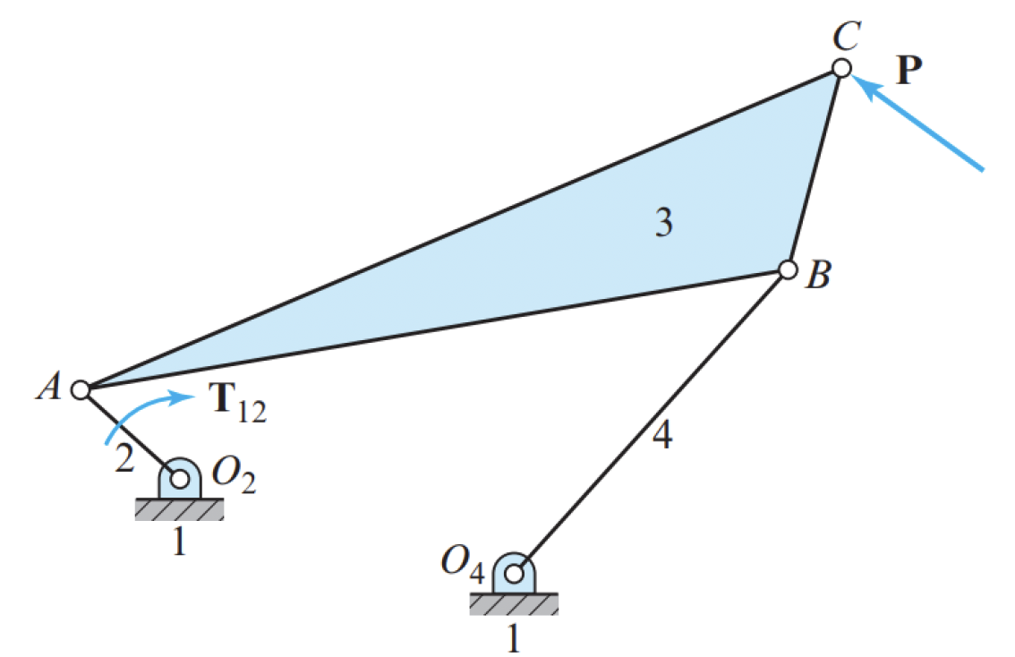
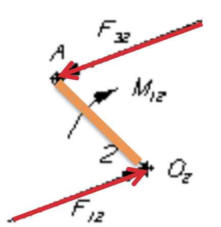
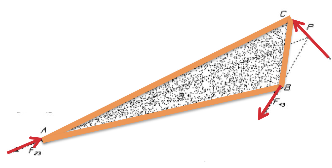
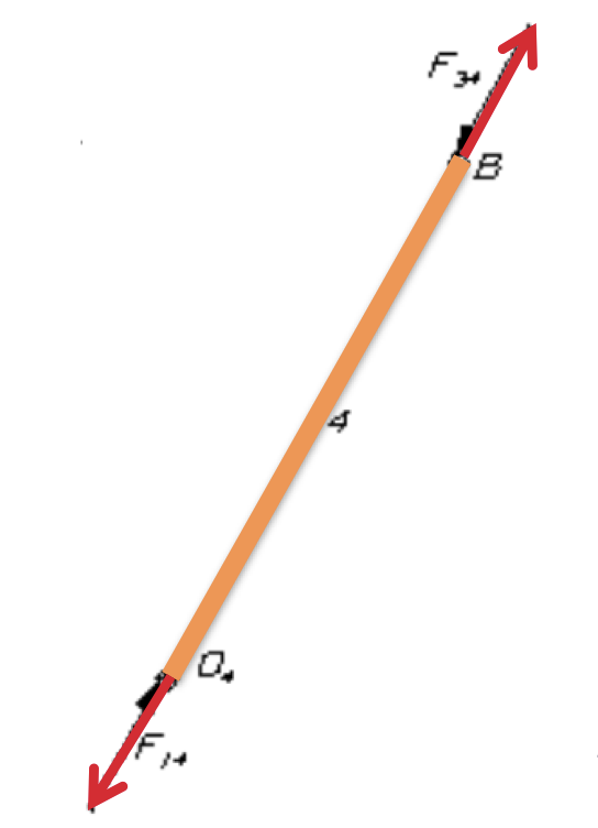
The figure shows a four-bar linkage and the external forces and torques exerted on or by the linkage in static equilibrium. Sketch the free-body diagram of each moving link. Do not attempt to show the magnitudes of the forces, except roughly, but do sketch them in their proper locations and approximate orientations.
Question 2
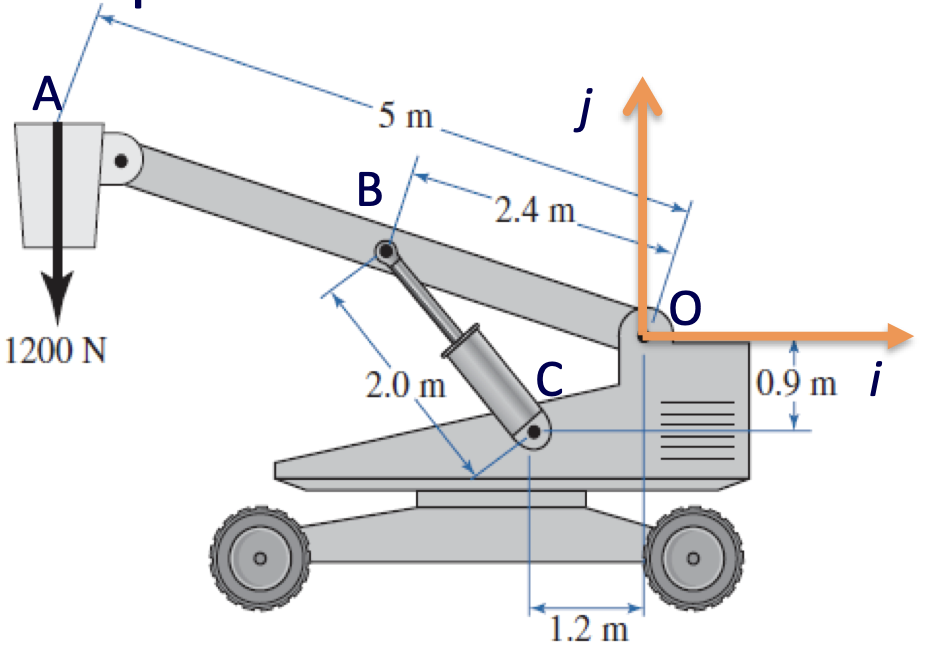
Determine the force required by the hydraulic cylinder to maintain the position of the bucket.
Answer
Solution
Step 1
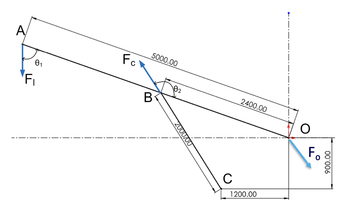
Draw a schematic diagram and choose a coordinate system.
Step 2
Write out the equilibrium equations, taking moments about point O.
\[\sum \mathbf{M}_O = \mathbf{R}_{AO} \times \mathbf{F}_l + \mathbf{R}_{BO} \times \mathbf{F}_c = \mathbf{0}\]Resolve each force into the component perpendicular to its moment arm:
\[\begin{align*} F_{l,\perp} &= F_l \sin(\theta_1) \\ F_{c,\perp} &= F_c \sin(\theta_2) \end{align*}\]Substitute the resolved force components into the moment equation:
\[\begin{align*} \sum M_O &= R_{AO} F_{l,\perp} - R_{BO} F_{c,\perp} = 0 \\ &= R_{AO} F_l \sin(\theta_1) - R_{BO} F_c \sin(\theta_2) = 0 \end{align*}\]Use millimetres consistently and define the triangle side lengths as
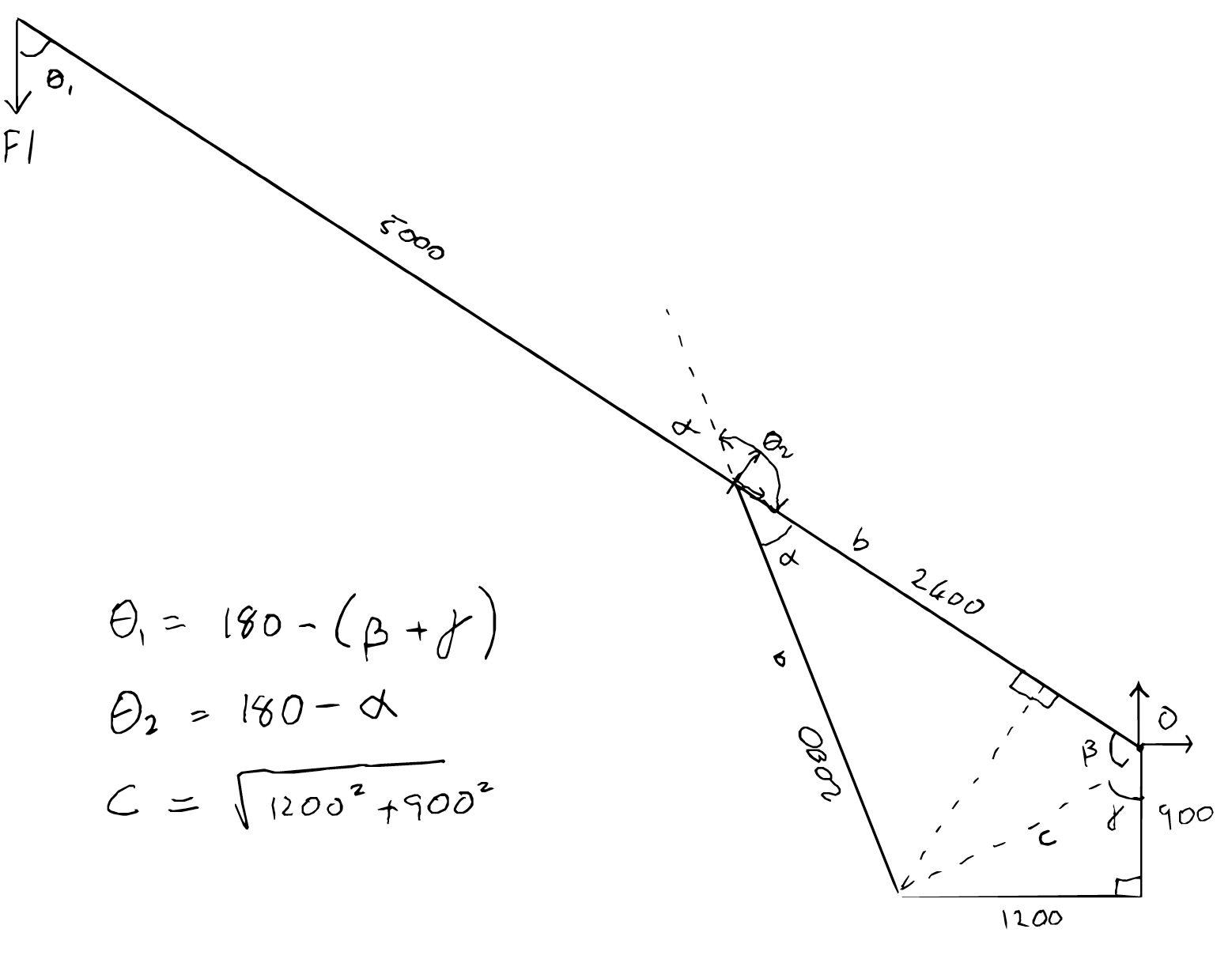
\[a=BC=2000\ \mathrm{mm}, \qquad b=BO=2400\ \mathrm{mm}, \qquad c=CO.\]First calculate $c$:
\[\begin{align*} c &= \sqrt{(1200\ \mathrm{mm})^2 + (900\ \mathrm{mm})^2} \\ c &= 1500\ \mathrm{mm} \\ \end{align*}\]Then calculate $\beta$:
\[\begin{align*} \cos{\beta} &= \frac{c^2 + b^2 - a^2}{2bc} \\ \beta &= 56.16^\circ \\[2em] \end{align*}\]Then calculate $\alpha$:
\[\begin{align*} \cos{\alpha} &= \frac{a^2 + b^2 - c^2}{2ab} \\ \alpha &= 38.53^\circ \\[2em] \end{align*}\]Then calculate $\gamma$:
\[\begin{align*} \tan \gamma &= \left(\frac{1200}{900}\right) \\ \gamma &= 53.13^\circ \\[2em] \end{align*}\]Finally, calculate $\theta_1$ and $\theta_2$. The angles shown in the diagram may be used for the moment magnitudes because supplementary angles have the same sine.
\[\begin{align*} \theta_1 &= 180^\circ - (\beta + \gamma) \\ &= 70.71^\circ \\[1em] \theta_2 &= 180^\circ - \alpha \\ &= 141.47^\circ \\ \end{align*}\]Step 3
Calculate $F_c$.
\(\begin{align*} F_c &= \frac{R_{AO} F_l \sin(\theta_1)}{R_{BO} \sin(\theta_2)} \\[1em] F_c &= 3788.20 N \end{align*}\)
Question 3
The uniform link shown rotates about the fixed pin at $O_2$. Determine the pin-reaction force $\mathbf{F}_{12}$ and the actuator torque $T_{12}$ required to produce the specified motion. Express the Newton-Euler equations in matrix form and then solve them.
| Quantity | Given information |
|---|---|
| Motion | Pure rotation about the fixed pin at $O_2$ |
| Link angle | $\theta_2=30^\circ$ counter-clockwise from the positive $x$-axis |
| Angular velocity | $\omega_2=4\ \mathrm{rad/s}$ counter-clockwise |
| Angular acceleration | $\alpha_2=2\ \mathrm{rad/s^2}$ counter-clockwise |
| Link length | $L=1.0\ \mathrm{m}$ |
| Link mass | $m_2=2.0\ \mathrm{kg}$ |
| Mass moment of inertia | $I_{G2}=m_2L^2/12$ |
| Applied force at $P$ | $\mathbf{F}_P=100\hat{\mathbf{i}}\ \mathrm{N}$ |
| Link weight | Ignore |
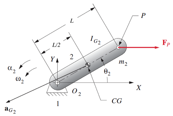
The diagram is schematic; use the dimensions given in the table above.
Answer
Solution
Step 1: Calculate the mass-centre acceleration
The mass centre is halfway along the uniform link:
\[\mathbf{R}_{G_2O_2} =\frac{L}{2} \left( \cos\theta_2\,\hat{\mathbf{i}} +\sin\theta_2\,\hat{\mathbf{j}} \right).\]At $\theta_2=30^\circ$,
\[\mathbf{R}_{G_2O_2} =0.4330\hat{\mathbf{i}} +0.2500\hat{\mathbf{j}}\ \mathrm{m}.\]For rotation about the fixed point $O_2$,
\[\mathbf{a}_{G_2} =\boldsymbol{\alpha}_2\times\mathbf{R}_{G_2O_2} -\omega_2^2\mathbf{R}_{G_2O_2}.\]Therefore,
\[\mathbf{a}_{G_2} =-7.428\hat{\mathbf{i}} -3.134\hat{\mathbf{j}}\ \mathrm{m/s^2}.\]The mass moment of inertia is
\[I_{G2} =\frac{m_2L^2}{12} =0.1667\ \mathrm{kg\,m^2}.\]Step 2: Define the moment-arm vectors
The vectors from $G_2$ to the pin at $O_2$ and to the applied force at $P$ are
\[\mathbf{R}_{12} =-0.4330\hat{\mathbf{i}} -0.2500\hat{\mathbf{j}}\ \mathrm{m},\] \[\mathbf{R}_{P} =0.4330\hat{\mathbf{i}} +0.2500\hat{\mathbf{j}}\ \mathrm{m}.\]Step 3: Write the Newton-Euler equations
The force balance in the $x$-direction is
\[F_{12x}+F_{Px}=m_2a_{G_2x}.\]The force balance in the $y$-direction is
\[F_{12y}+F_{Py}=m_2a_{G_2y}.\]Taking moments about $G_2$ gives
\[T_{12} +\left(R_{12x}F_{12y}-R_{12y}F_{12x}\right) +\left(R_{Px}F_{Py}-R_{Py}F_{Px}\right) =I_{G2}\alpha_2.\]Step 4: Assemble the simultaneous system
Using
\[[B]= \begin{bmatrix} F_{12x}&F_{12y}&T_{12} \end{bmatrix}^{T},\]the equations become
\[\begin{bmatrix} 1&0&0\\ 0&1&0\\ -R_{12y}&R_{12x}&1 \end{bmatrix} \begin{bmatrix} F_{12x}\\ F_{12y}\\ T_{12} \end{bmatrix} = \begin{bmatrix} m_2a_{G_2x}-F_{Px}\\ m_2a_{G_2y}-F_{Py}\\ I_{G2}\alpha_2-\left(R_{Px}F_{Py}-R_{Py}F_{Px}\right) \end{bmatrix}.\]After substituting the known values,
\[\begin{bmatrix} 1&0&0\\ 0&1&0\\ 0.2500&-0.4330&1 \end{bmatrix} \begin{bmatrix} F_{12x}\\ F_{12y}\\ T_{12} \end{bmatrix} = \begin{bmatrix} -114.856\\ -6.268\\ 25.333 \end{bmatrix}.\]Step 5: Solve for the reaction force and actuator torque
The solution is
\[F_{12x}=-114.86\ \mathrm{N},\] \[F_{12y}=-6.27\ \mathrm{N},\]and
\[T_{12}=51.33\ \mathrm{N\,m}.\]Therefore,
\[\mathbf{F}_{12} =-114.86\hat{\mathbf{i}} -6.27\hat{\mathbf{j}}\ \mathrm{N},\]with an actuator torque of $51.33\ \mathrm{N\,m}$ counter-clockwise.
Question 4
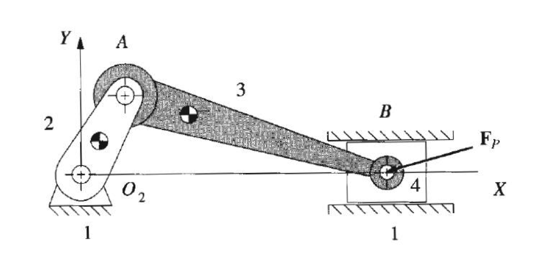
Determine the torque $T_{12}$ applied to crank 2 to maintain the crank-slider linkage in static equilibrium.
| Quantity | Given information |
|---|---|
| Applied force magnitude | $P=0.9\ \mathrm{kN}$ |
| Applied force direction | Horizontally to the left |
| Crank length | $R_{AO2}=75\ \mathrm{mm}$ |
| Connecting-link length | $R_{BA}=350\ \mathrm{mm}$ |
| Crank angle | $105^\circ$ counter-clockwise from the positive $x$-axis |
| Analysis condition | Static equilibrium |
Answer
Solution
Step 1
Calculate $\phi$ using the sine law.
\[\begin{align*} &\frac{R_{AO2}}{\sin \phi} = \frac{R_{BA}}{\sin 105^\circ} \\[1em] &\phi = \sin^{-1} \left(\frac{R_{AO2}}{R_{BA}} \sin 105^\circ\right) \\[1em] &\phi =11.95^\circ \end{align*}\]Step 2
Draw a free body diagram.

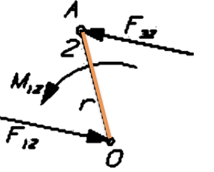
To calculate the torque $T_{12}$, we need to determine $\mathbf{F}_{32}$ and $\mathbf{R}_{AO_2}$. First, use the equilibrium of link 4 to calculate the magnitudes of $F_{34}$ and $F_{14}$.
\[\begin{align*} &F_{34} \cos \phi - P = 0\\ &F_{34} = 919.92\ \mathrm{N} \approx 920\ \mathrm{N} \\[1em] &F_{14} - F_{34} \sin \phi = 0\\ &F_{14} = 190.41\ \mathrm{N} \end{align*}\]Because link 3 is a two-force member, $\mathbf{F}_{32}$ is equal in magnitude and opposite in direction to $\mathbf{F}_{34}$:
\[\begin{align*} \mathbf{F}_{32} &= -\mathbf{F}_{34} = F_{34}(-\cos\phi\,\hat{\mathbf{i}}+\sin\phi\,\hat{\mathbf{j}})\\ &=919.92(-\cos 11.95^\circ\,\hat{\mathbf{i}} +\sin 11.95^\circ\,\hat{\mathbf{j}})\ \mathrm{N}. \end{align*}\]Before calculating $T_{12}$, determine $\mathbf{R}_{AO_2}$:
\[\begin{align*} \mathbf{R}_{AO_2} &=R_{AO2}(\cos 105^\circ\,\hat{\mathbf{i}} +\sin 105^\circ\,\hat{\mathbf{j}})\\ &=0.075(\cos 105^\circ\,\hat{\mathbf{i}} +\sin 105^\circ\,\hat{\mathbf{j}})\ \mathrm{m}. \end{align*}\]Isolate link 2 and apply moment equilibrium about $O_2$, taking counter-clockwise torque as positive. The pin reaction at $O_2$ has zero moment about $O_2$:
\[\begin{align*} T_{12}+\left(\mathbf{R}_{AO_2}\times\mathbf{F}_{32}\right) \cdot\hat{\mathbf{k}}&=0,\\ T_{12}&=-61.51\ \mathrm{N\,m}. \end{align*}\]Therefore, the required actuator-torque magnitude is $61.51\ \mathrm{N\,m}$ clockwise.