Dynamic Force Analysis - Fourbar Linkage
We will be deriving a system of equations that enable us to calculate forces and torques in a fourbar linkage. For information about dynamic analysis of other mechanisms please see Dynamic Force Analysis
We are interested in knowing the forces at each of the joints and the torque applied, given that we know the length, mass, mass moment of inertia, angle, angular velocity, accelerations of the links and the forces applied. Therefore, with reference to the diagram below we know or can calculate the following; $\mathbf{R_{12}}$, $\mathbf{R_{32}}$, $\mathbf{R_{23}}$, $\mathbf{R_{43}}$, $\mathbf{R_{34}}$, $\mathbf{R_{14}}$ $\mathbf{R_{p}}$, $m_2$, $m_3$, $m_4$, $I_{g_2}$, $I_{g_3}$, $I_{g_4}$, $\theta_2$, $\theta_3$, $\theta_4$, $\omega_2$, $\omega_3$, $a_{G_2}$, $a_{G_3}$, $a_{G_4}$, $\alpha_2$, $\alpha_3$, $\alpha_4$, $\alpha_{G_2}$, $\alpha_{G_3}$, $\alpha_{G_4}$, $\mathbf{F_{P}}$ and $\mathbf{T_4}$.
The forces, $\mathbf{F_{12}}$, $\mathbf{F_{32}}$, $\mathbf{F_{43}}$, $\mathbf{F_{14}}$ as well as the torque, $\mathbf{T_{12}}$ are unknown and this is what we will be calculating. We assume that all unknown forces and torques are positive in direction.
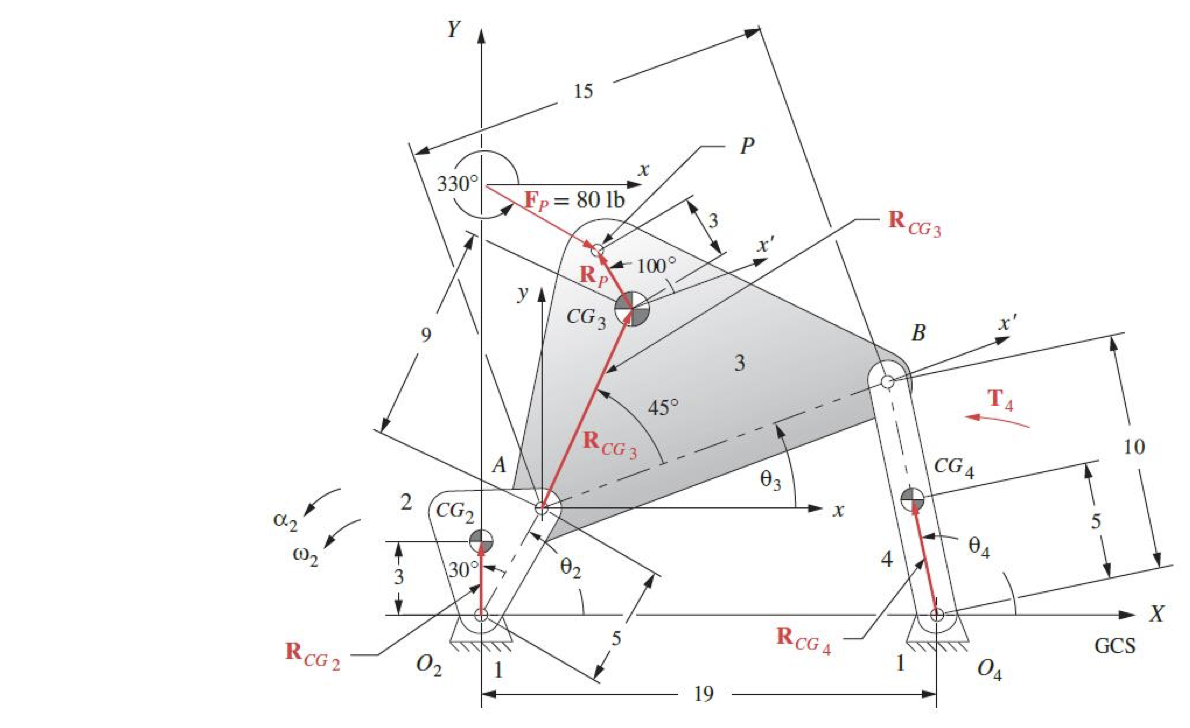
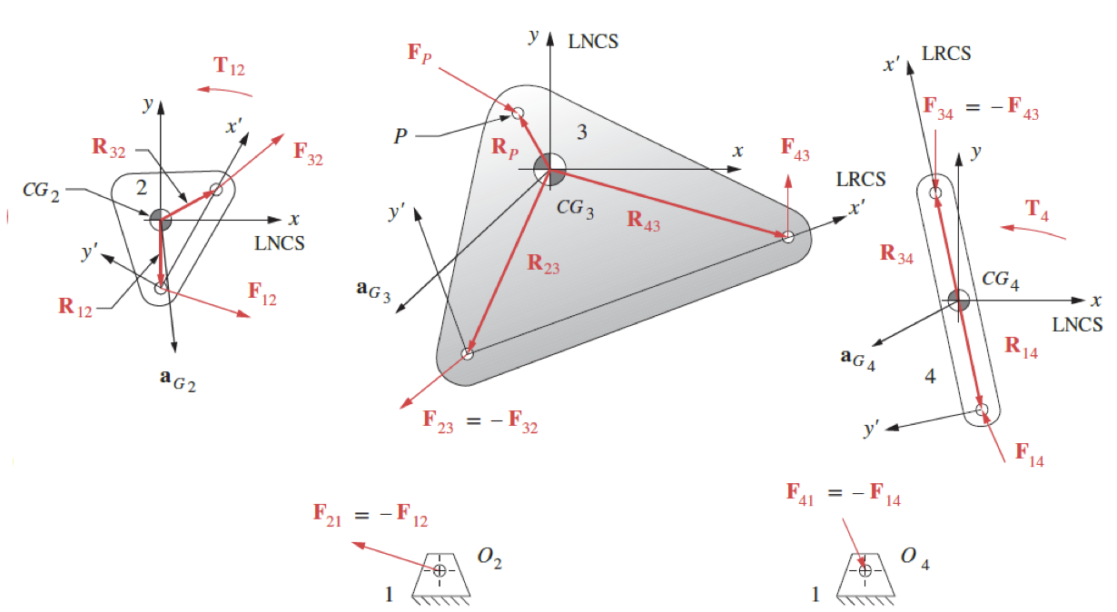
Examine the fourbar link mechanism shown in Figure 1 above and the freebody diagram of this shown in Figure 2.
An external force $\mathbf{F_p}$ is applied on link 3 at point $P$, also an external torque $\mathbf{T_4}$ is applied on link 4. Note the CG of each of the members and the local nonrotating coordinates placed at each of these.
For link 2 the equations are,
\[\begin{gathered} F_{12x}+F_{32x}=m_2 a_{G_{2x}} \\ F_{12y}+F_{32y}=m_2 a_{G_{2y}} \\ T_{12}+\left(R_{12x} F_{12y}-R_{12y} F_{12x}\right)+\left(R_{32x} F_{32y}-R_{32y} F_{32x}\right)=I_{G2} \alpha_2 \end{gathered}\]and for link 3,
\[\begin{gathered} F_{43x} - F_{32x} + F_{Px} = m_3 a_{G_{3x}} \\ F_{43y} - F_{32y} + F_{Py} = m_3 a_{G_{3y}} \\ (R_{43x}F_{43y} - R_{43y}F_{43x}) - (R_{23x}F_{32y} - R_{23y}F_{32x}) + (R_{Px}F_{Py} - R_{Py}F_{Px}) = I_{G3}\alpha_{3}\\ \end{gathered}\]for link 4 we substitute the reaction force $\mathbf{-F_{43}}$ for $\mathbf{F_{34}}$,
\[\begin{gathered} F_{14x} - F_{43x} = m_4 a_{G_{x}} \\ F_{14y} - F_{43y} = m_4 a_{G_{4y}} \\ \left(R_{14x} F_{14y} - R_{14y} F_{14x}\right) - \left(R_{34x} F_{43y}- R_{34y} F_{43x}\right) + T_4 = I_{G_4} \alpha_4 \end{gathered}\]As before the system of equations can be put in matrix form,
\[{\left[\begin{array}{ccccccccc} 1 & 0 & 1 & 0 & 0 & 0 & 0 & 0 & 0 \\ 0 & 1 & 0 & 1 & 0 & 0 & 0 & 0 & 0 \\ -R_{12y} & R_{12x} & -R_{32y} & R_{32x} & 0 & 0 & 0 & 0 & 1 \\ 0 & 0 & -1 & 0 & 1 & 0 & 0 & 0 & 0 \\ 0 & 0 & 0 & -1 & 0 & 1 & 0 & 0 & 0 \\ 0 & 0 & R_{23y} & -R_{23x} & -R_{43y} & R_{43x} & 0 & 0 & 0 \\ 0 & 0 & 0 & 0 & -1 & 0 & 1 & 0 & 0 \\ 0 & 0 & 0 & 0 & 0 & -1 & 0 & 1 & 0 \\ 0 & 0 & 0 & 0 & R_{34y} & -R_{34x} & -R_{14y} & R_{14x} & 0 \end{array}\right] \times\left[\begin{array}{c} F_{12x} \\ F_{12y} \\ F_{32x} \\ F_{32y} \\ F_{43x} \\ F_{43y} \\ F_{14x} \\ F_{14y} \\ T_{12} \end{array}\right]=}\\ \left[\begin{array}{c} m_2 a_{G_{2x}} \\ m_2 a_{G_{2y}} \\ I_{G_2} \alpha_2 \\ m_3 a_{G_{3x}}-F_{Px} \\ m_3 a_{G_{3y}}-F_{Py} \\ I_{G_3} \alpha_3-R_{Px} F_{Py}+R_{Py} F_{Px} \\ m_4 a_{G_{4x}} \\ m_4 a_{G_{4y}} \\ I_{G_4} \alpha_4-T_4 \end{array}\right] \nonumber\]and solved for the unknowns, $F_{12x}$, $F_{12y}$, $F_{32x}$, $F_{32y}$, $F_{43x}$, $F_{43y}$, $F_{14x}$, $F_{14y}$ and $T_{12}$.
Fourbar Linkage - Matlab Code
The following MATLAB code may be used to calculate the unknown values.
1
2
3
4
5
6
7
8
9
10
11
12
13
14
15
16
17
18
19
20
21
22
23
24
25
26
27
28
29
30
31
32
33
34
35
36
37
38
39
40
41
42
43
44
45
46
47
48
49
50
51
52
53
54
55
56
57
58
59
60
61
62
63
64
65
% Given scalar parameters
m2 = ; % Mass of link 2
m3 = ; % Mass of link 3
m4 = ; % Mass of link 4
IG2 = ; % Mass moment of inertia of link 2
IG3 = ; % Mass moment of inertia of link 3
IG4 = ; % Mass moment of inertia of link 4
R12 = ; % Distance from CG of link 2 to joint
R32 = ; % Distance from CG of link 3 to joint
R23 = ; % Distance from CG of link 3 to joint
R43 = ; % Distance from CG of link 4 to joint
R34 = ; % Distance from CG of link 4 to joint
R14 = ; % Distance from CG of link 4 to joint
Rp = ; % Distance from CG of link 3 to force application point
FPx = ; % Force applied along x-axis at point P
FPy = ; % Force applied along y-axis at point P
aG2x = ; % Acceleration of CG of link 2 along x-axis
aG2y = ; % Acceleration of CG of link 2 along y-axis
aG3x = ; % Acceleration of CG of link 3 along x-axis
aG3y = ; % Acceleration of CG of link 3 along y-axis
aG4x = ; % Acceleration of CG of link 4 along x-axis
aG4y = ; % Acceleration of CG of link 4 along y-axis
alpha2 = ; % Angular acceleration of link 2
alpha3 = ; % Angular acceleration of link 3
alpha4 = ; % Angular acceleration of link 4
alphaG2 = ; % Angular acceleration of CG of link 2
alphaG3 = ; % Angular acceleration of CG of link 3
alphaG4 = ; % Angular acceleration of CG of link 4
T4 = ; % Applied torque on link 4

% Coefficient matrix
A = [1, 0, 1, 0, 0, 0, 0, 0, 0;
     0, 1, 0, 1, 0, 0, 0, 0, 0;
     -R12(2), R12(1), -R32(2), R32(1), 0, 0, 0, 0, 1;
     0, 0, -1, 0, 1, 0, 0, 0, 0;
     0, 0, 0, -1, 0, 1, 0, 0, 0;
     0, 0, R23(2), -R23(1), -R43(2), R43(1), 0, 0, 0;
     0, 0, 0, 0, -1, 0, 1, 0, 0;
     0, 0, 0, 0, 0, -1, 0, 1, 0;
     0, 0, 0, 0, R34(2), -R34(1), -R14(2), R14(1), 0];

% Right-hand side of the equations
rhs = [m2 * aG2x;
       m2 * aG2y;
       IG2 * alpha2;
       m3 * aG3x - FPx;
       m3 * aG3y - FPy;
       IG3 * alpha3 - (Rp(1) * FPy - Rp(2) * FPx);
       m4 * aG4x;
       m4 * aG4y;
       IG4 * alpha4 - T4];

% Solve the system of equations
unknowns = A \ rhs;

% Extracting the unknowns
F12x = unknowns(1);
F12y = unknowns(2);
F32x = unknowns(3);
F32y = unknowns(4);
F43x = unknowns(5);
F43y = unknowns(6);
F14x = unknowns(7);
F14y = unknowns(8);
T12 = unknowns(9);