Week 2 Tutorial - Kinematic Analysis of Mechanisms
Part A: Position Analysis
Question 1: Conventional four-bar linkage
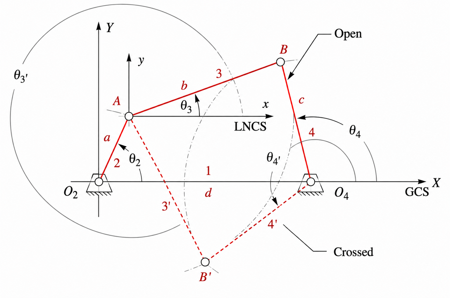
For the four-bar linkage shown above, use
| Parameter | Value |
|---|---|
| $d$ | 100 mm |
| $a$ | 40 mm |
| $b$ | 120 mm |
| $c$ | 80 mm |
| $\theta_2$ | $40^\circ$ |
Using the vector-loop method, determine all real values of $\theta_3$ and $\theta_4$. Identify the open and crossed configurations.
Answer
-
First evaluate the constants
\[\begin{aligned} A &= 2cd - 2ac\cos\theta_2 = 11097.32 \\ B &= -2ac\sin\theta_2 = -4113.84 \\ C &= a^2 - b^2 + c^2 + d^2 - 2ad\cos\theta_2 = -2528.36 \end{aligned}\] \[\begin{aligned} D &= 2ab\cos\theta_2 - 2bd = -16645.97 \\ E &= 2ab\sin\theta_2 = 6170.76 \\ F &= a^2 + b^2 + d^2 - c^2 - 2ad\cos\theta_2 = 13471.64 \end{aligned}\]Because each term is a product of two lengths, the constants $A$ to $F$ have units of $\text{mm}^2$.
-
For $\theta_4$, use
\[t_4 = \frac{-2B \pm \sqrt{(2B)^2 - 4(C-A)(A+C)}}{2(C-A)}\]Therefore,
\[\theta_{4,1}=2\tan^{-1}(t_{4,1}), \qquad \theta_{4,2}=2\tan^{-1}(t_{4,2})\]Numerically,
\[t_{4,1}=0.5466, \qquad t_{4,2}=-1.1505\]so
\[\theta_{4,1}=57.32^\circ, \qquad \theta_{4,2}=-98.00^\circ\] -
For $\theta_3$, use
\[t_3 = \frac{-2E \pm \sqrt{(2E)^2 - 4(F-D)(D+F)}}{2(F-D)}\]Therefore,
\[\theta_{3,1}=2\tan^{-1}(t_{3,1}), \qquad \theta_{3,2}=2\tan^{-1}(t_{3,2})\]Numerically,
\[t_{3,1}=0.1790, \qquad t_{3,2}=-0.5888\]so
\[\theta_{3,1}=20.30^\circ, \qquad \theta_{3,2}=-60.98^\circ\] -
The two configurations are
The root pairs are selected by substituting each possible combination back into the original loop-closure equations:
\[\begin{aligned} r_x &= a\cos\theta_2+b\cos\theta_3-c\cos\theta_4-d \\ r_y &= a\sin\theta_2+b\sin\theta_3-c\sin\theta_4 \end{aligned}\]A valid pair must give $r_x\approx0$ and $r_y\approx0$. Testing all four combinations gives
$\theta_3$ $\theta_4$ $r_x$ (mm) $r_y$ (mm) Result $20.30^\circ$ $57.32^\circ$ $-0.01$ $0.01$ Closes $20.30^\circ$ $-98.00^\circ$ $54.32$ $146.57$ Does not close $-60.98^\circ$ $57.32^\circ$ $-54.34$ $-146.56$ Does not close $-60.98^\circ$ $-98.00^\circ$ $-0.01$ $0.00$ Closes The small non-zero residuals in the valid rows are caused by rounding the angles to two decimal places. This check shows that the acute $\theta_3$ root must pair with the positive $\theta_4$ root, while the two negative roots must pair together.
Configuration $\theta_3$ $\theta_4$ Open $20.30^\circ$ $57.32^\circ$ Crossed $-60.98^\circ$ $-98.00^\circ$ To name the configurations, sketch the two valid geometries or calculate the joint positions. For $(20.30^\circ,57.32^\circ)$, the coupler remains above the fixed link, so this is the open configuration. For $(-60.98^\circ,-98.00^\circ)$, the coupler crosses the fixed link between the ground pivots, so this is the crossed configuration.
Question 2: Four-bar crank-slider linkage
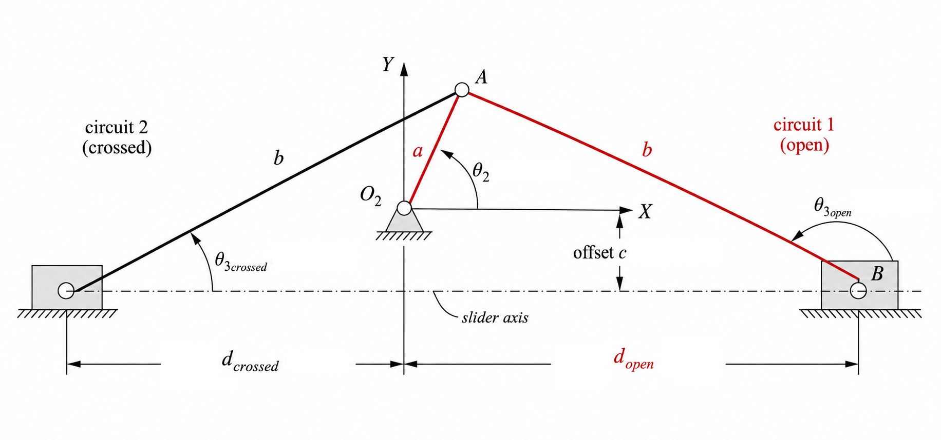
For the four-bar crank-slider linkage shown above, use
| Parameter | Value |
|---|---|
| $a$ | 35 mm |
| $b$ | 110 mm |
| $c$ | -15 mm |
| $\theta_2$ | $50^\circ$ |
Use the open configuration only, defined here as the branch with positive slider position $d$. Determine $\theta_3$ and $d$.
Answer
-
Here, $c$ is the signed vertical offset of the slider axis relative to $O_2$. Because the slider axis is below $O_2$ in this example, $c=-15\text{ mm}$. Use the position equations
\[\sin\theta_3=\frac{a\sin\theta_2-c}{b}\] \[d=a\cos\theta_2-b\cos\theta_3\] -
Substituting the data gives
\[\sin\theta_3=\frac{35\sin50^\circ-(-15)}{110}=0.3801\] -
The two angular branches are
\[\theta_3=\sin^{-1}(0.3801)=22.34^\circ\] \[\theta_3=180^\circ-22.34^\circ=157.66^\circ\]The sine equation alone cannot identify the open configuration because the two supplementary angles have the same sine. They give different horizontal positions, however, because their cosines have opposite signs. Evaluate $d$ for both branches:
\[\begin{aligned} d_{22.34^\circ} &=35\cos50^\circ-110\cos22.34^\circ \\ &=-79.25\text{ mm} \\ d_{157.66^\circ} &=35\cos50^\circ-110\cos157.66^\circ \\ &=124.24\text{ mm} \end{aligned}\]Here, $d$ is measured from $O_2$ along the positive slider axis. Also, $\theta_3$ describes the direction of link $b$ from slider $B$ towards joint $A$. For $\theta_3=22.34^\circ$, $\cos\theta_3>0$, so the link points to the right from $B$ to $A$ and $B$ must lie to the left of $O_2$. This gives $d<0$ and corresponds to the crossed circuit shown in the diagram. For $\theta_3=157.66^\circ$, $\cos\theta_3<0$, so the link points to the left from $B$ to $A$ and $B$ lies to the right of $O_2$. This gives $d>0$ and matches the open circuit shown in red. Therefore, under the definition given in the question, the open branch is
\[\theta_3=157.66^\circ, \qquad d=124.24\text{ mm}.\] -
Therefore, for the open configuration
Quantity Value $\theta_3$ $157.66^\circ$ $d$ $124.24\text{ mm}$
Question 3: Four-bar crank-slider linkage
Starting from the vector loop equation
\[\mathbf{R}_A+\mathbf{R}_{BA}-\mathbf{R}_{BO_2}=0,\]show that
\[\sin\theta_3=\frac{a\sin\theta_2-c}{b}\]and
\[d=a\cos\theta_2-b\cos\theta_3.\]Answer
-
Start from the vector loop equation
\[\mathbf{R}_A+\mathbf{R}_{BA}-\mathbf{R}_{BO_2}=0\] -
In complex form this becomes
\[a e^{j\theta_2} - b e^{j\theta_3} - (d + jc) = 0\] -
Expand with Euler’s relation $e^{j\theta}=\cos\theta+j\sin\theta$:
\[a(\cos\theta_2+j\sin\theta_2)-b(\cos\theta_3+j\sin\theta_3)-(d+jc)=0\] -
Separate real and imaginary parts:
\[a\cos\theta_2-b\cos\theta_3-d=0\] \[a\sin\theta_2-b\sin\theta_3-c=0\] -
Rearrange the imaginary equation first:
\[a\sin\theta_2-b\sin\theta_3-c=0\] \[b\sin\theta_3=a\sin\theta_2-c\] \[\sin\theta_3=\frac{a\sin\theta_2-c}{b}\] -
Now rearrange the real equation:
\[a\cos\theta_2-b\cos\theta_3-d=0\] \[d=a\cos\theta_2-b\cos\theta_3\]
Part B: Velocity Analysis
Question 4: Conventional four-bar linkage
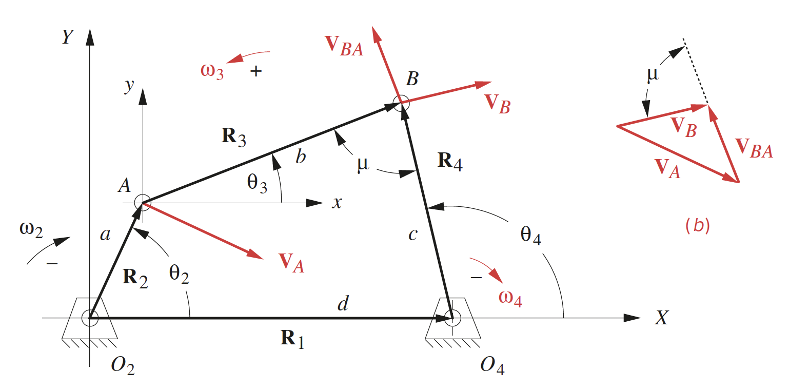
Use the following instantaneous configuration and input speed.
| Parameter | Value |
|---|---|
| $d$ | 100 mm |
| $a$ | 40 mm |
| $b$ | 120 mm |
| $c$ | 80 mm |
| $\theta_2$ | $40^\circ$ |
| $\theta_3$ | $20.30^\circ$ |
| $\theta_4$ | $57.32^\circ$ |
| $\omega_2$ | 25 rad/s |
Determine $\omega_3$, $\omega_4$, the speed of point $A$, the relative speed between $B$ and $A$, and the speed of point $B$.
Answer
-
Use the velocity equations
\[\omega_3=\omega_2\frac{a\sin(\theta_4-\theta_2)}{b\sin(\theta_3-\theta_4)}\] \[\omega_4=\omega_2\frac{a\sin(\theta_2-\theta_3)}{c\sin(\theta_4-\theta_3)}\]Once $\omega_3$ and $\omega_4$ are known, the point-velocity equations are
\[\mathbf{V}_A=a\omega_2(-\sin\theta_2+j\cos\theta_2)\] \[\mathbf{V}_{BA}=b\omega_3(-\sin\theta_3+j\cos\theta_3)\] \[\mathbf{V}_B=c\omega_4(-\sin\theta_4+j\cos\theta_4)\] -
Substituting the given configuration gives
\[\omega_3=25\frac{40\sin(57.32^\circ-40^\circ)}{120\sin(20.30^\circ-57.32^\circ)}=-4.120456\text{ rad/s}\approx-4.12\text{ rad/s}\] \[\omega_4=25\frac{40\sin(40^\circ-20.30^\circ)}{80\sin(57.32^\circ-20.30^\circ)}=6.998396\text{ rad/s}\approx7.00\text{ rad/s}\] -
The speed magnitudes then follow:
\[|\mathbf{V}_A|=a\omega_2=40(25)=1000.00\text{ mm/s}\] \[|\mathbf{V}_{BA}|=b|\omega_3|=120(4.120456)=494.45\text{ mm/s}\] \[|\mathbf{V}_B|=c|\omega_4|=80(6.998396)=559.87\text{ mm/s}\]Therefore
Quantity Value $\omega_3$ $-4.12\text{ rad/s}$ $\omega_4$ $7.00\text{ rad/s}$ $\lvert \mathbf{V}_A \rvert$ $1000.00\text{ mm/s}$ $\lvert \mathbf{V}_{BA} \rvert$ $494.45\text{ mm/s}$ $\lvert \mathbf{V}_B \rvert$ $559.87\text{ mm/s}$ The negative sign on $\omega_3$ shows that link 3 rotates opposite to the assumed positive angular direction.
Question 5: Four-bar crank-slider linkage
Use the following open-configuration state.
| Parameter | Value |
|---|---|
| $a$ | 35 mm |
| $b$ | 110 mm |
| $c$ | -15 mm |
| $\theta_2$ | $50^\circ$ |
| $\theta_3$ | $157.66^\circ$ |
| $d$ | $124.24\text{ mm}$ |
| $\omega_2$ | 20 rad/s |
Determine $\omega_3$ and the slider velocity $\dot d$.
Answer
-
Use the velocity relations
\[\omega_3=\frac{a\cos\theta_2}{b\cos\theta_3}\omega_2\] \[\dot d=-a\omega_2\sin\theta_2+b\omega_3\sin\theta_3\] -
Substituting the given state gives
\[\omega_3=\frac{35\cos50^\circ}{110\cos157.66^\circ}(20)=-4.4224\text{ rad/s}\approx-4.42\text{ rad/s}\] -
Then
\[\dot d=-35(20)\sin50^\circ+110(-4.4224)\sin157.66^\circ=-721.14\text{ mm/s}\]Therefore
Quantity Value $\omega_3$ $-4.42\text{ rad/s}$ $\dot d$ $-721.14\text{ mm/s}$
Question 6: Four-bar crank-slider linkage velocity
Starting from the differentiated vector loop equation
\[\frac{d}{dt}\left(\mathbf{R}_A+\mathbf{R}_{BA}-\mathbf{R}_{BO_2}\right)=0,\]show that
\[\omega_3=\frac{a\cos\theta_2}{b\cos\theta_3}\omega_2\]and
\[\dot d=-a\omega_2\sin\theta_2+b\omega_3\sin\theta_3.\]Answer
-
Start from the differentiated vector loop equation
\[\frac{d}{dt}\left(\mathbf{R}_A+\mathbf{R}_{BA}-\mathbf{R}_{BO_2}\right)=0\] -
Write the vectors in complex form:
\[\mathbf{R}_A=a e^{j\theta_2}, \qquad \mathbf{R}_{BA}=-b e^{j\theta_3}, \qquad \mathbf{R}_{BO_2}=d+jc\] -
In complex form, the differentiated loop is
\[ja\omega_2e^{j\theta_2}-jb\omega_3e^{j\theta_3}-\dot d=0\] -
Expand with Euler’s relation $e^{j\theta}=\cos\theta+j\sin\theta$:
\[ja\omega_2(\cos\theta_2+j\sin\theta_2)-jb\omega_3(\cos\theta_3+j\sin\theta_3)-\dot d=0\] -
Simplify the products by using $j(\cos\theta+j\sin\theta)=-\sin\theta+j\cos\theta$:
\[a\omega_2(-\sin\theta_2+j\cos\theta_2)-b\omega_3(-\sin\theta_3+j\cos\theta_3)-\dot d=0\] -
Separate real and imaginary parts:
\[-a\omega_2\sin\theta_2+b\omega_3\sin\theta_3-\dot d=0\] \[a\omega_2\cos\theta_2-b\omega_3\cos\theta_3=0\] -
Rearranging the real equation gives
\[\dot d=-a\omega_2\sin\theta_2+b\omega_3\sin\theta_3\] -
Rearranging the imaginary equation gives
\[b\omega_3\cos\theta_3=a\omega_2\cos\theta_2\] \[\omega_3=\frac{a\cos\theta_2}{b\cos\theta_3}\omega_2\]
Part C: Acceleration Analysis
Question 7: Conventional four-bar linkage
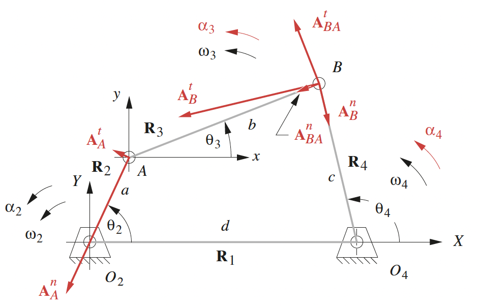
Use the following instantaneous state.
| Parameter | Value |
|---|---|
| $d$ | 100 mm |
| $a$ | 40 mm |
| $b$ | 120 mm |
| $c$ | 80 mm |
| $\theta_2$ | $40^\circ$ |
| $\theta_3$ | $20.30^\circ$ |
| $\theta_4$ | $57.32^\circ$ |
| $\omega_2$ | 25 rad/s |
| $\omega_3$ | $-4.12\text{ rad/s}$ |
| $\omega_4$ | $7.00\text{ rad/s}$ |
| $\alpha_2$ | 15 rad/s$^2$ |
Determine $\alpha_3$, $\alpha_4$, and the $x$ and $y$ components of $\mathbf{A}_{A}$, $\mathbf{A}_{BA}$ and $\mathbf{A}_{B}$.
Answer
-
Use the solved acceleration equations from the lecture:
\[\begin{aligned} \alpha_3={}& \frac{(a\alpha_2\sin\theta_2+a\omega_2^2\cos\theta_2+b\omega_3^2\cos\theta_3-c\omega_4^2\cos\theta_4)(c\cos\theta_4)}{(c\sin\theta_4)(b\cos\theta_3)-(b\sin\theta_3)(c\cos\theta_4)} \\ &-\frac{(c\sin\theta_4)(a\alpha_2\cos\theta_2-a\omega_2^2\sin\theta_2-b\omega_3^2\sin\theta_3+c\omega_4^2\sin\theta_4)}{(c\sin\theta_4)(b\cos\theta_3)-(b\sin\theta_3)(c\cos\theta_4)} \end{aligned}\] \[\begin{aligned} \alpha_4={}& \frac{(a\alpha_2\sin\theta_2+a\omega_2^2\cos\theta_2+b\omega_3^2\cos\theta_3-c\omega_4^2\cos\theta_4)(b\cos\theta_3)}{(c\sin\theta_4)(b\cos\theta_3)-(b\sin\theta_3)(c\cos\theta_4)} \\ &-\frac{(b\sin\theta_3)(a\alpha_2\cos\theta_2-a\omega_2^2\sin\theta_2-b\omega_3^2\sin\theta_3+c\omega_4^2\sin\theta_4)}{(c\sin\theta_4)(b\cos\theta_3)-(b\sin\theta_3)(c\cos\theta_4)} \end{aligned}\] -
Substitute the given lengths, angles, angular velocities and $\alpha_2$ directly into the solved lecture equations:
\[\begin{aligned} \alpha_3 &=\frac{ \begin{aligned} &\big[40(15)\sin40^\circ+40(25^2)\cos40^\circ +120((-4.12)^2)\cos20.30^\circ \\ &\qquad-80(7.00^2)\cos57.32^\circ\big](80\cos57.32^\circ) \\ &-(80\sin57.32^\circ)\big[40(15)\cos40^\circ-40(25^2)\sin40^\circ \\ &\qquad-120((-4.12)^2)\sin20.30^\circ +80(7.00^2)\sin57.32^\circ\big] \end{aligned} }{ \begin{aligned} &(80\sin57.32^\circ)(120\cos20.30^\circ) \\ &\qquad-(120\sin20.30^\circ)(80\cos57.32^\circ) \end{aligned} } \\ &=296.1074\text{ rad/s}^2 \\ &\approx296.11\text{ rad/s}^2, \end{aligned}\] \[\begin{aligned} \alpha_4 &=\frac{ \begin{aligned} &\big[40(15)\sin40^\circ+40(25^2)\cos40^\circ +120((-4.12)^2)\cos20.30^\circ \\ &\qquad-80(7.00^2)\cos57.32^\circ\big](120\cos20.30^\circ) \\ &-(120\sin20.30^\circ)\big[40(15)\cos40^\circ-40(25^2)\sin40^\circ \\ &\qquad-120((-4.12)^2)\sin20.30^\circ +80(7.00^2)\sin57.32^\circ\big] \end{aligned} }{ \begin{aligned} &(80\sin57.32^\circ)(120\cos20.30^\circ) \\ &\qquad-(120\sin20.30^\circ)(80\cos57.32^\circ) \end{aligned} } \\ &=470.1535\text{ rad/s}^2 \\ &\approx470.15\text{ rad/s}^2. \end{aligned}\] -
Use the point-acceleration equations given in the lecture:
\[\mathbf{A}_A=a\alpha_2(-\sin\theta_2+j\cos\theta_2)-a\omega_2^2(\cos\theta_2+j\sin\theta_2)\] \[\mathbf{A}_{BA}=b\alpha_3(-\sin\theta_3+j\cos\theta_3)-b\omega_3^2(\cos\theta_3+j\sin\theta_3)\] \[\mathbf{A}_B=c\alpha_4(-\sin\theta_4+j\cos\theta_4)-c\omega_4^2(\cos\theta_4+j\sin\theta_4)\] -
Substitute the values directly into these three equations:
\[\begin{aligned} \mathbf{A}_A & =40(15)(-\sin40^\circ+j\cos40^\circ) \\ &\quad -40(25^2)(\cos40^\circ+j\sin40^\circ) \\ &=-19536.78-15610.06j\text{ mm/s}^2, \end{aligned}\] \[\begin{aligned} \mathbf{A}_{BA} & =120(296.1074)(-\sin20.30^\circ+j\cos20.30^\circ) \\ &\quad -120((-4.12)^2)(\cos20.30^\circ+j\sin20.30^\circ) \\ &=-14238.04+32619.22j\text{ mm/s}^2, \end{aligned}\] \[\begin{aligned} \mathbf{A}_B & =80(470.1535)(-\sin57.32^\circ+j\cos57.32^\circ) \\ &\quad -80(7.00^2)(\cos57.32^\circ+j\sin57.32^\circ) \\ &=-33774.82+17009.16j\text{ mm/s}^2. \end{aligned}\]The real parts are the $x$-components and the imaginary parts are the $y$-components.
-
The results are
Quantity Value $\alpha_3$ $296.11\text{ rad/s}^2$ $\alpha_4$ $470.15\text{ rad/s}^2$ $A_{Ax}$ $-19536.78\text{ mm/s}^2$ $A_{Ay}$ $-15610.06\text{ mm/s}^2$ $A_{BAx}$ $-14238.04\text{ mm/s}^2$ $A_{BAy}$ $32619.22\text{ mm/s}^2$ $A_{Bx}$ $-33774.82\text{ mm/s}^2$ $A_{By}$ $17009.16\text{ mm/s}^2$
Question 8: Four-bar crank-slider linkage
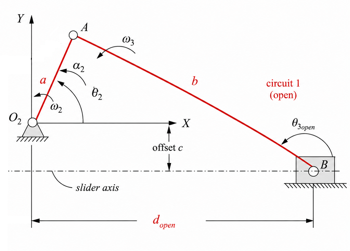
Use the following open-configuration state.
| Parameter | Value |
|---|---|
| $a$ | 35 mm |
| $b$ | 110 mm |
| $c$ | -15 mm |
| $\theta_2$ | $50^\circ$ |
| $\theta_3$ | $157.66^\circ$ |
| $\omega_2$ | 20 rad/s |
| $\omega_3$ | $-4.42\text{ rad/s}$ |
| $\alpha_2$ | 12 rad/s$^2$ |
Determine $\alpha_3$ and the slider acceleration $\ddot d$.
Answer
-
Use the acceleration relations:
\[\alpha_3=\frac{a\alpha_2\cos\theta_2-a\omega_2^2\sin\theta_2+b\omega_3^2\sin\theta_3}{b\cos\theta_3}\] \[\ddot d=-a\alpha_2\sin\theta_2-a\omega_2^2\cos\theta_2+b\alpha_3\sin\theta_3+b\omega_3^2\cos\theta_3\] -
Substituting the data gives
\[\alpha_3=\frac{35(12)\cos50^\circ-35(20^2)\sin50^\circ+110((-4.42)^2)\sin157.66^\circ}{110\cos157.66^\circ}=94.73\text{ rad/s}^2\] \[\ddot d=-35(12)\sin50^\circ-35(20^2)\cos50^\circ+110(94.7262)\sin157.66^\circ+110((-4.42)^2)\cos157.66^\circ=-7347.86\text{ mm/s}^2\]Therefore
Quantity Value $\alpha_3$ $94.73\text{ rad/s}^2$ $\ddot d$ $-7347.86\text{ mm/s}^2$
Question 9: Four-bar crank-slider linkage acceleration
Starting from the twice-differentiated vector loop equation
\[\frac{d^2}{dt^2}\left(\mathbf{R}_A+\mathbf{R}_{BA}-\mathbf{R}_{BO_2}\right)=0,\]show that
\[\alpha_3=\frac{a\alpha_2\cos\theta_2-a\omega_2^2\sin\theta_2+b\omega_3^2\sin\theta_3}{b\cos\theta_3}\]and
\[\ddot d=-a\alpha_2\sin\theta_2-a\omega_2^2\cos\theta_2+b\alpha_3\sin\theta_3+b\omega_3^2\cos\theta_3.\]Answer
-
Start from the twice-differentiated vector loop equation
\[\frac{d^2}{dt^2}\left(\mathbf{R}_A+\mathbf{R}_{BA}-\mathbf{R}_{BO_2}\right)=0\] -
Write the vectors in complex form:
\[\mathbf{R}_A=a e^{j\theta_2}, \qquad \mathbf{R}_{BA}=-b e^{j\theta_3}, \qquad \mathbf{R}_{BO_2}=d+jc\] -
In complex form, the twice-differentiated loop is
\[a(j\alpha_2-\omega_2^2)e^{j\theta_2}-b(j\alpha_3-\omega_3^2)e^{j\theta_3}-\ddot d=0\] -
Expand with Euler’s relation $e^{j\theta}=\cos\theta+j\sin\theta$:
\[a(j\alpha_2-\omega_2^2)(\cos\theta_2+j\sin\theta_2)-b(j\alpha_3-\omega_3^2)(\cos\theta_3+j\sin\theta_3)-\ddot d=0\] -
Simplify the products by using
\[(j\alpha-\omega^2)(\cos\theta+j\sin\theta) = (-\alpha\sin\theta-\omega^2\cos\theta) + j(\alpha\cos\theta-\omega^2\sin\theta)\] \[\begin{aligned} &a(-\alpha_2\sin\theta_2-\omega_2^2\cos\theta_2+j(\alpha_2\cos\theta_2-\omega_2^2\sin\theta_2)) \\ &\quad-b(-\alpha_3\sin\theta_3-\omega_3^2\cos\theta_3+j(\alpha_3\cos\theta_3-\omega_3^2\sin\theta_3))-\ddot d=0 \end{aligned}\] -
Separate real and imaginary parts:
\[-a\alpha_2\sin\theta_2-a\omega_2^2\cos\theta_2+b\alpha_3\sin\theta_3+b\omega_3^2\cos\theta_3-\ddot d=0\] \[a\alpha_2\cos\theta_2-a\omega_2^2\sin\theta_2-b\alpha_3\cos\theta_3+b\omega_3^2\sin\theta_3=0\] -
Rearranging the real equation gives
\[\ddot d=-a\alpha_2\sin\theta_2-a\omega_2^2\cos\theta_2+b\alpha_3\sin\theta_3+b\omega_3^2\cos\theta_3\] -
Rearranging the imaginary equation gives
\[b\alpha_3\cos\theta_3=a\alpha_2\cos\theta_2-a\omega_2^2\sin\theta_2+b\omega_3^2\sin\theta_3\] \[\alpha_3=\frac{a\alpha_2\cos\theta_2-a\omega_2^2\sin\theta_2+b\omega_3^2\sin\theta_3}{b\cos\theta_3}\]