Lecture 3: Dynamic Fundamentals
[For Illustration Only]
Force analysis connects a mechanism’s known motion to the forces and torques in its links. Static equilibrium and free-body diagrams provide the basis for this analysis. Centre of gravity and mass moment of inertia describe how the distribution of mass affects weight and inertia forces.
Kinematic analysis finds position, velocity and acceleration without considering the forces that cause motion. Dynamic force analysis uses the accelerations to calculate joint forces and the actuator torque. This is called inverse dynamics because the motion is known and the forces that cause it are unknown.
The mass, centre of gravity and mass moment of inertia of every moving link are also needed. During early design, these properties may be estimated from the expected shape, material density and dimensions.
The calculated forces help determine the final shape and size of each link. Dynamic design is therefore repeated: estimated parts give estimated loads, and changing the parts requires a new force calculation.
A force is a vector with magnitude and direction. Several forces can be replaced by one resultant force. One force can also be separated into perpendicular components.
In two dimensions, a force at angle $\theta$ from the positive $x$-axis can be written as $F_x=F\cos\theta$ and $F_y=F\sin\theta$. The chosen axes determine the signs. The magnitude and direction are
\[F=\sqrt{F_x^2+F_y^2},\qquad \theta=\operatorname{atan2}(F_y,F_x).\]Work is the energy transferred when a force moves through a distance. Power is the rate of doing work. Torque is the turning effect of a force. These quantities are related but describe different effects.
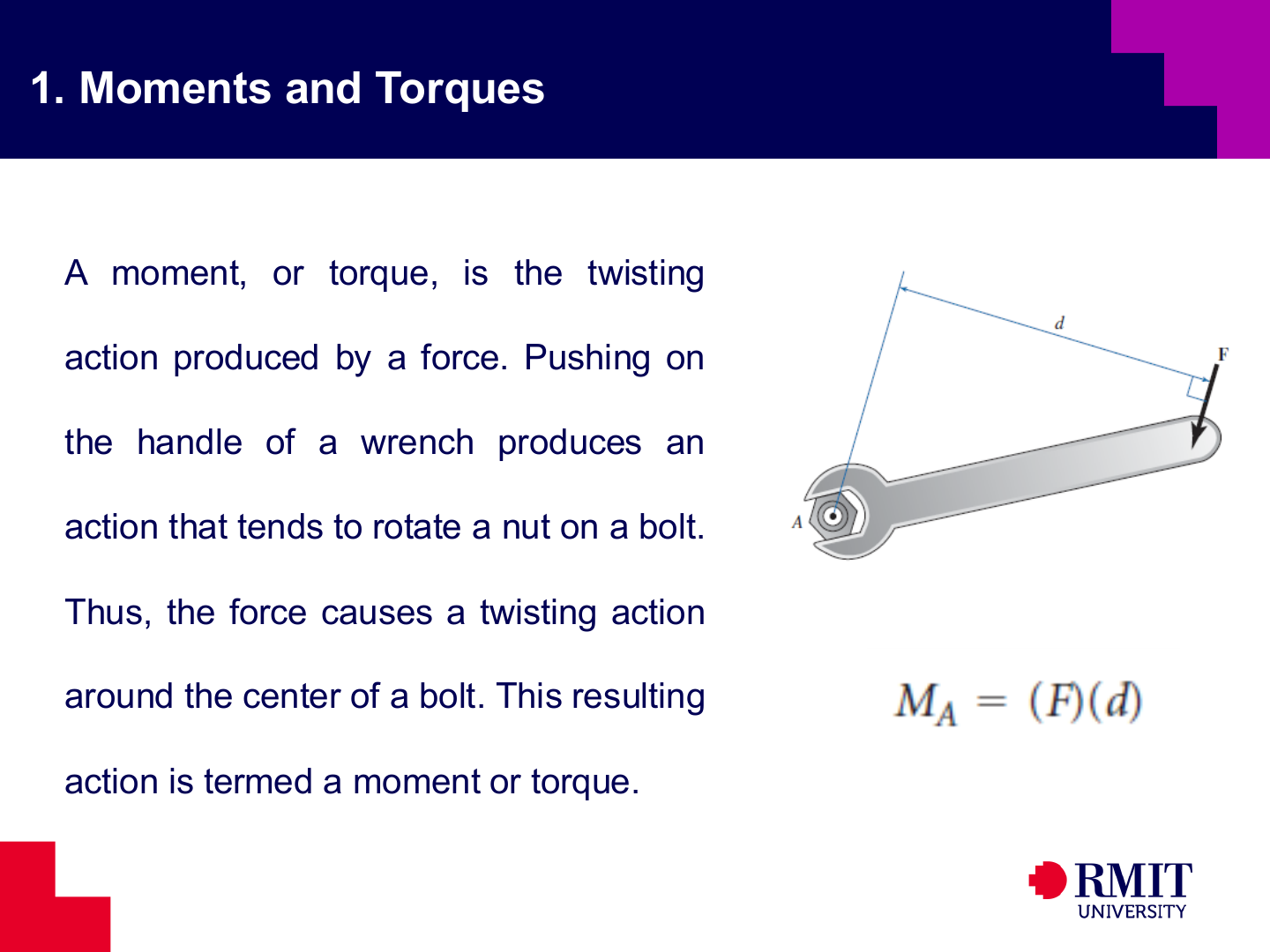
The moment of a force about a point measures its tendency to cause rotation. In vector form, \(\mathbf{M}_A=\mathbf{r}_{OP}\times\mathbf{F},\) and in a planar problem its magnitude is $M_O=Fd_\perp$, where $d_\perp$ is the perpendicular distance from the point to the force’s line of action. A force applied farther from the pivot therefore produces more torque.
Newton’s first law describes inertia: a body remains at rest or continues moving at constant velocity unless acted on by a resultant external force.
Newton’s second law relates the resultant external force to the rate of change of linear momentum,
\[\sum\mathbf{F}=\frac{d\mathbf{p}}{dt},\]For a constant-mass body, this reduces to
\[\sum\mathbf{F}=m\mathbf{a}.\]For planar rigid-body rotation about an axis through the mass centre, the corresponding moment equation is
\[\sum M_G=I_G\alpha.\]Newton’s third law states that interaction forces form equal and opposite pairs on different bodies. They do not cancel on the free-body diagram of one link because only one force in the pair acts on that link. They cancel only when both bodies are included in the same system.
Static force analysis applies when acceleration is zero or when the inertia terms $m\mathbf{a}_G$ and $I_G\alpha$ are very small compared with the other loads. This is often suitable for slowly operated clamps, latches, support linkages, pliers and cutters. The mechanism may move between positions, but each selected position is treated as being in equilibrium.
Static equilibrium does not always mean that a mechanism never moves. A slowly moving mechanism can be analysed at several positions if acceleration effects remain small.
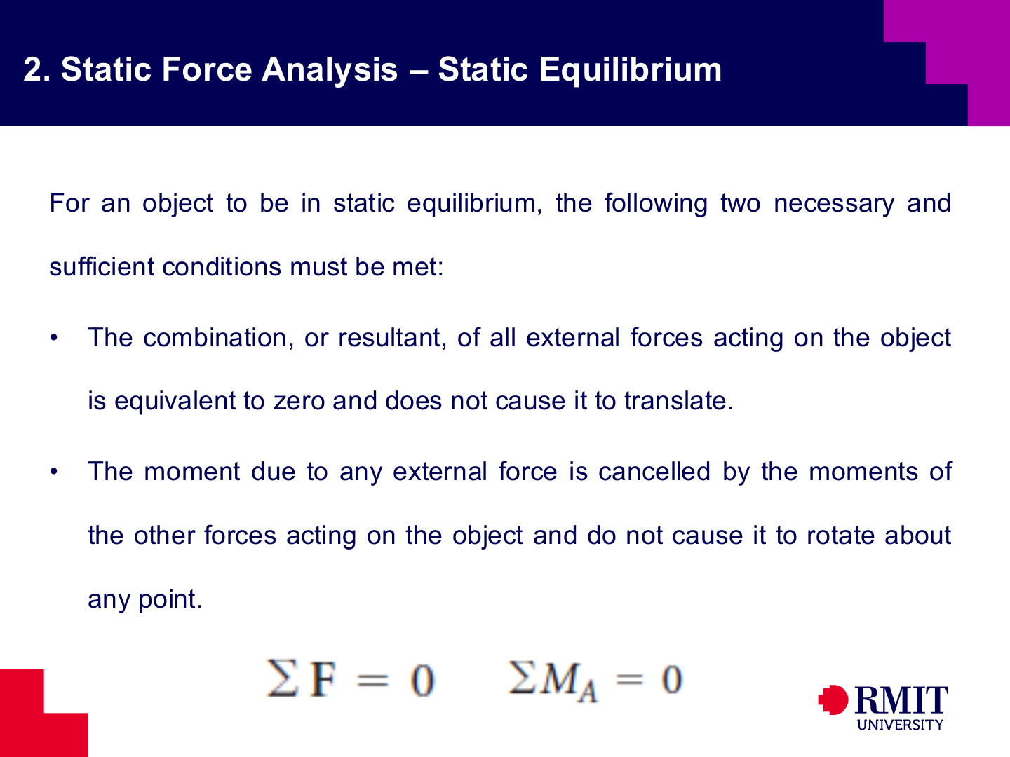
A planar rigid body is in static equilibrium only when its total force and total moment are both zero:
\[\sum F_x=0,\qquad \sum F_y=0,\qquad \sum M_A=0.\]The force equations prevent linear acceleration, while the moment equation prevents angular acceleration. Both conditions are needed. A body can have zero total force but a non-zero couple, or zero moment about one point but a non-zero total force.
Moments can be calculated about any convenient point. Choose a point through which unknown forces act so those forces produce no moment about that point. This reduces the number of unknowns. The two force equations can then be used to find the remaining reaction components.
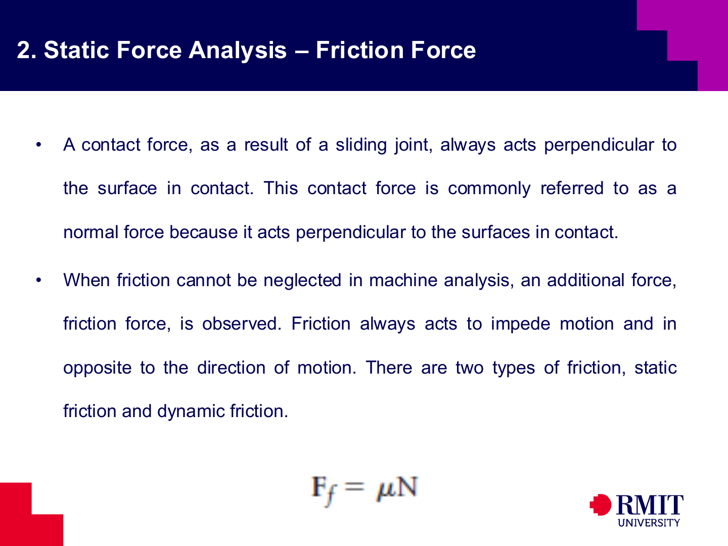
A contact produces a normal reaction perpendicular to the surfaces. If friction is important, add a tangential force that opposes the actual or expected relative motion.
Static friction satisfies
\[\lvert F_f \rvert \leq \mu_s N,\]while sliding friction is commonly modelled as
\[F_f = \mu_k N,\]with the friction force acting opposite to the sliding velocity.
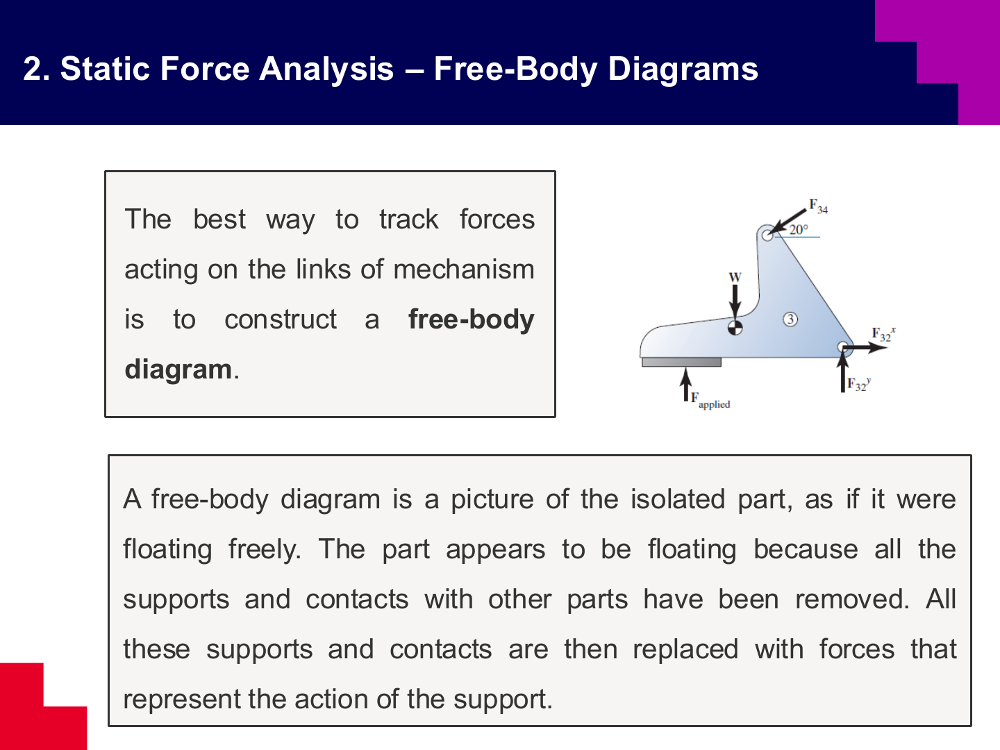
A free-body diagram separates one body from its surroundings. Replace every removed support or contact with the force and, when needed, the couple moment that it applies. Show only forces acting on the selected body. Keep body forces such as weight, and add connection forces where other bodies have been removed.
The support type determines the unknown reactions. A planar pin provides two force components but no reaction couple. A frictionless slider provides a reaction normal to its guide. A fixed support can provide two force components and a couple.
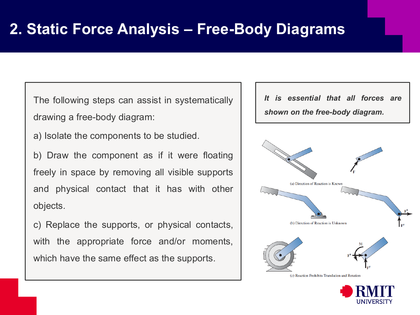
A systematic free-body-diagram procedure is:
- Define the body or group of bodies to isolate.
- Remove all supports and contacts.
- Replace each removed support or contact with the correct reaction components.
- Add applied loads, weight, and applied couples.
- Mark the dimensions and angles needed for moments.
A missing force makes the model incomplete. A force drawn on the wrong body gives an incorrect action-reaction pair.
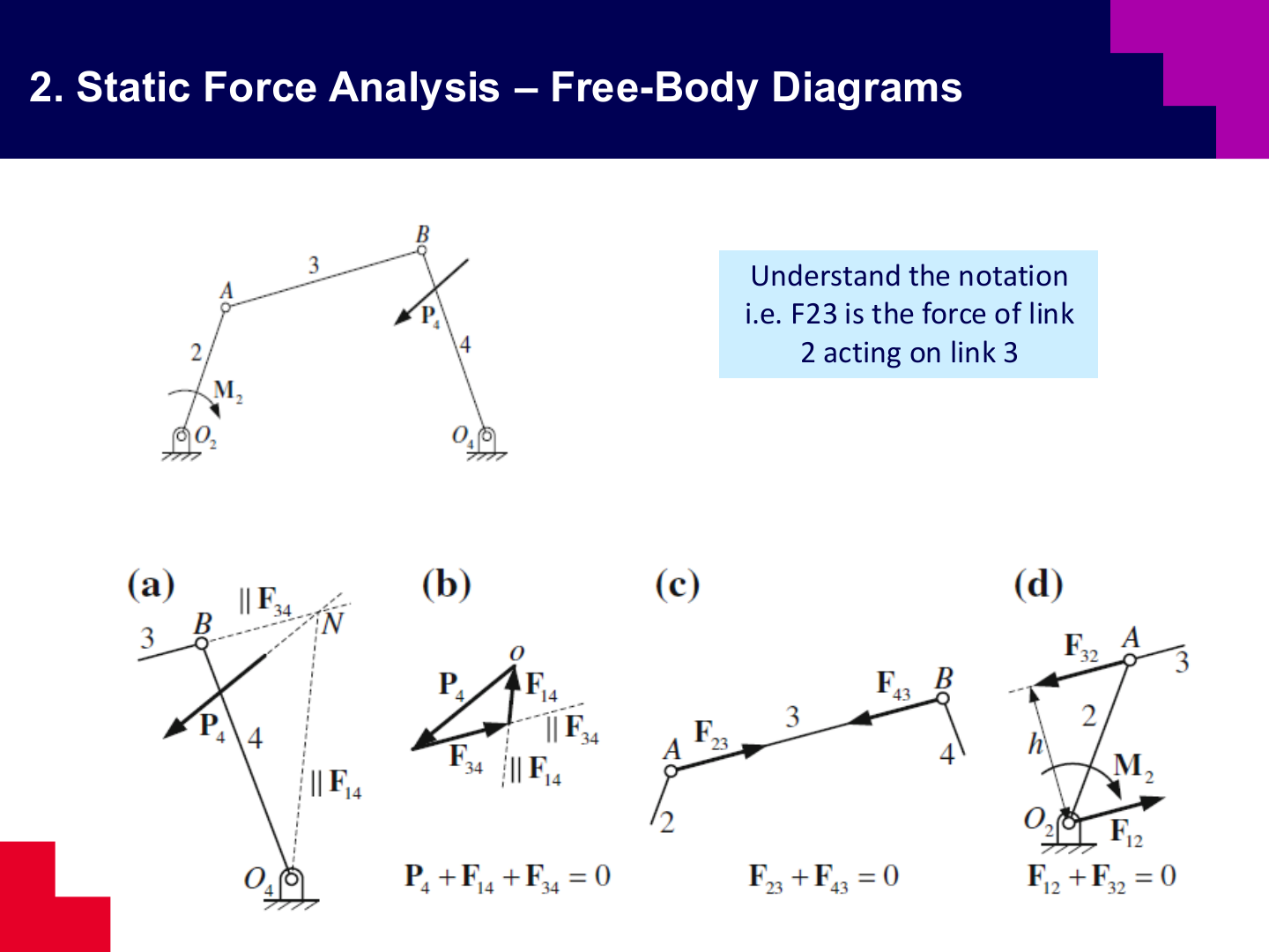
The notation $\mathbf{F}_{ij}$ means the force applied by link $i$ to link $j$. Newton’s third law gives $\mathbf{F}_{ij}=-\mathbf{F}_{ji}$. Use one unknown vector for each pin and apply its negative to the connected link.
Link 3 is a two-force member in this static model, so its two pin forces are collinear with the line joining $A$ and $B$. Link 4 carries an additional applied load, $\mathbf{P_4}$, and is therefore a three-force member.
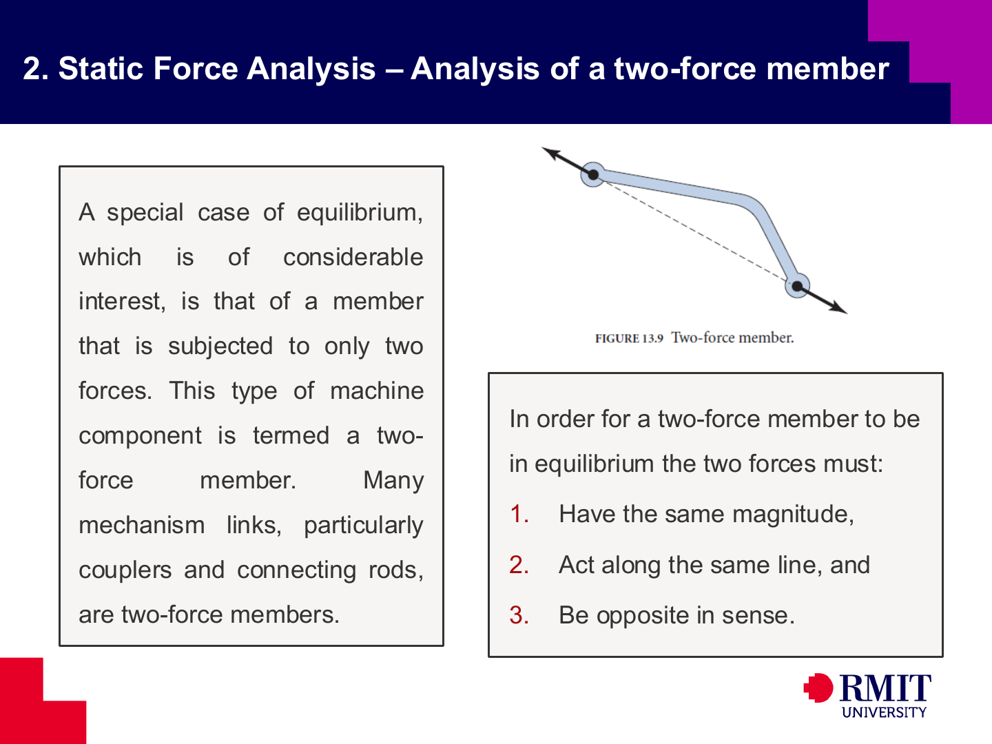
A two-force member has forces at only two points and no external couple. For equilibrium, the two forces must have the same magnitude, opposite directions and the same line of action. Identifying a two-force member reduces two unknown reaction components to one unknown force along the member.
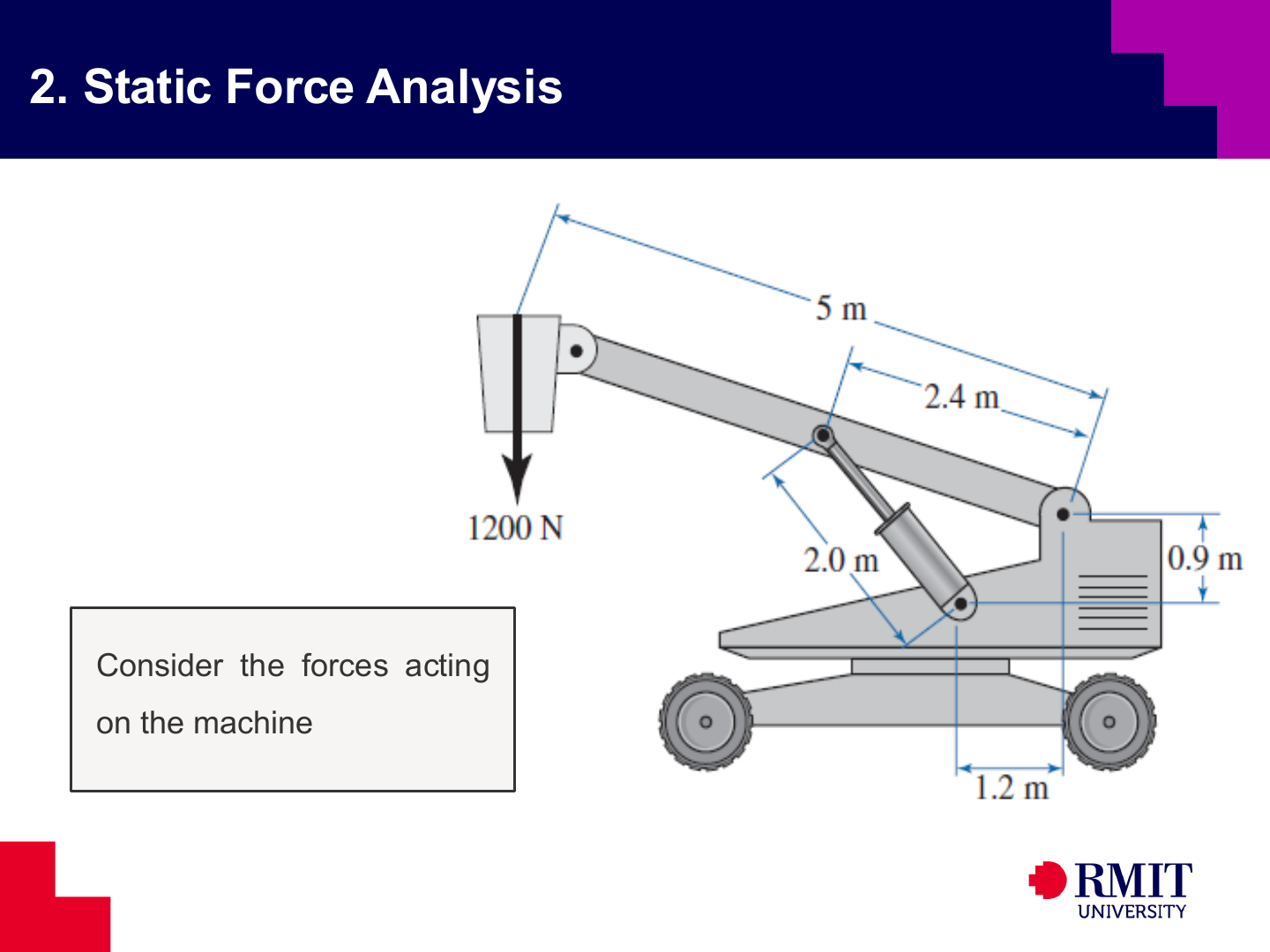
The crane problem can be simplified into a boom pinned to the base, a hydraulic cylinder connected between two pins, and a $1200\,\mathrm{N}$ downward load. The cylinder is a two-force member, so its force acts along the cylinder axis.
A useful solution sequence is:
- Isolate the boom.
- Take moments about its base pivot to find the cylinder force.
- Use force equilibrium to determine the base reaction.
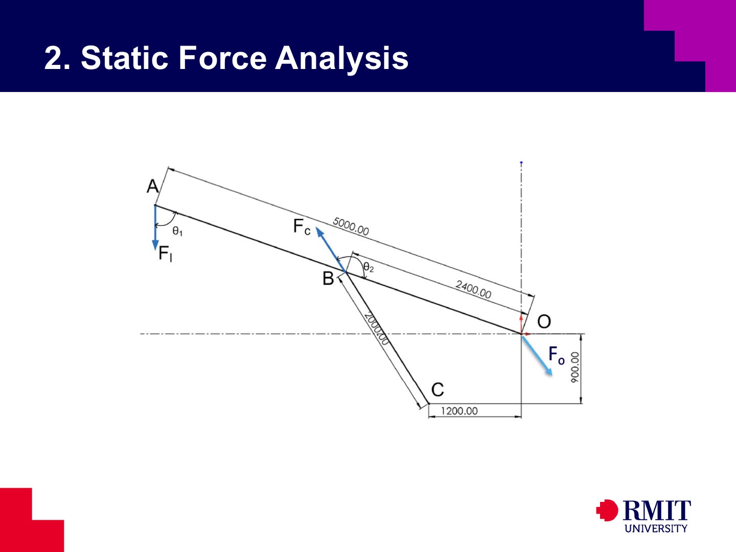
For the boom, the external actions are the applied load $F_l$, the cylinder force $F_c$, and the pivot reaction $F_o$.
Because the cylinder is a two-force member, $F_c$ acts along the line joining $B$ and $C$. A pin support can exert force in two independent directions, so $F_o$ generally has both horizontal and vertical components.
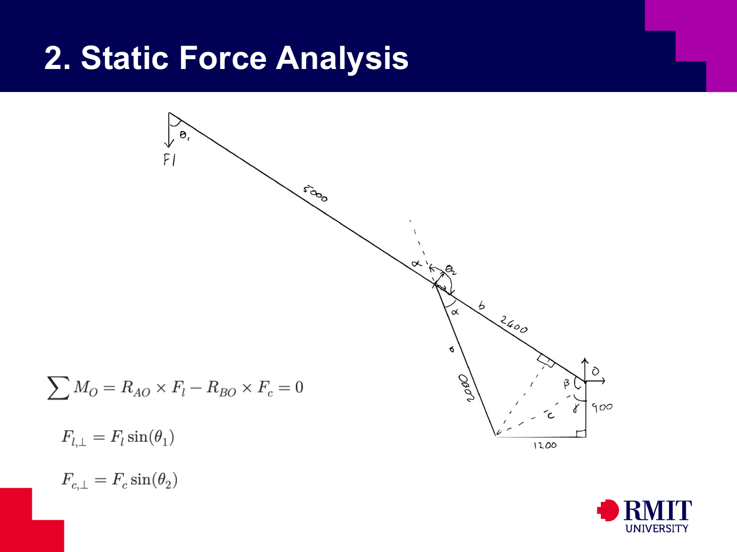
Use the link lengths and offsets to form triangles and find the boom and cylinder angles. Then calculate each moment using $M=Fd_\perp$ or the planar cross product $M_O=r_xF_y-r_yF_x$. Use one sign convention consistently for clockwise and anticlockwise moments.
The centre of gravity is the point where the body’s weight, $W=mg$, is treated as acting. Its position affects the moment of the weight about each joint. In a uniform gravitational field, the centre of gravity and centre of mass are at the same point.
The translational Newton-Euler equation uses the acceleration of the mass centre, $\mathbf{a}_G$, not the acceleration of another point on the link. Position vectors in moment equations are therefore usually measured from $G$. Planar dynamic analysis needs the mass centre, total mass and mass moment of inertia about the mass centre.
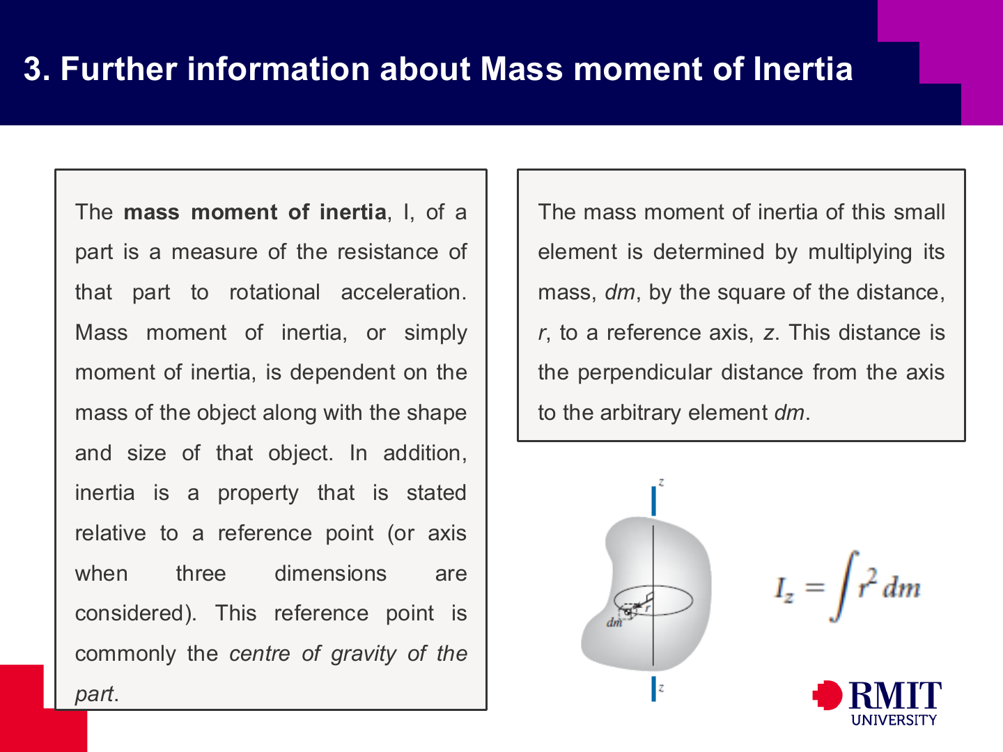
Mass moment of inertia measures a body’s resistance to angular acceleration about a chosen axis. For a small mass element at perpendicular distance $r$, \(dI=r^2\,dm,\) Mass farther from the axis makes a greater contribution. Moment of inertia therefore depends on both total mass and how the mass is distributed. Its units are $\mathrm{kg\,m^2}$.
Two bodies with the same mass can have very different moments of inertia if their mass is distributed differently. The radius of gyration $k$ expresses the same property through \(I=mk^2,\) The value $k$ is the distance from the axis where the total mass could be placed to give the same moment of inertia.
[For Illustration Only]

[For Illustration Only]

[For Illustration Only]
The principal reference for these topics is Robert L. Norton’s Design of Machinery.
[For Illustration Only]
Dynamic force analysis applies the Newton-Euler equations to each moving link. One rotating link gives three scalar equations. A crank-slider gives a connected set of equations because neighbouring links share equal and opposite joint forces. Combining the equations into one linear system allows all joint-force components and the actuator torque to be found together.
Dynamic force analysis is needed when link acceleration makes inertia important. Kinematic analysis gives $\mathbf{a}_G$ and $\alpha$ at each mechanism position. Force analysis then finds the joint reactions and actuator torque that produce this motion and balance the applied loads.
Weight may be ignored when the link accelerations are much larger than $g$, making the effect of gravity small. Include weight as an external force $m\mathbf{g}$ at the centre of gravity when links are heavy, move slowly or have small accelerations. Compare the sizes of the loads when making this decision.
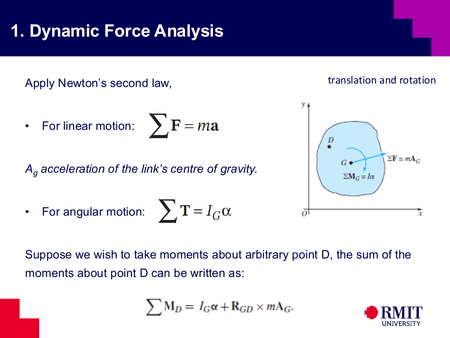
For a planar rigid link, translation and rotation are calculated $\sum\mathbf{F}=m\mathbf{a}_G$, $\sum M_G=I_G\alpha$.
The force equation gives separate $x$- and $y$-component equations. The moment equation gives a third scalar equation. Each moving planar link therefore provides three Newton-Euler equations.
If moments are taken about another point $D$, the linear inertia produces an additional moment: \(\sum M_D=I_G\alpha+\mathbf{r}_{DG}\times m\mathbf{a}_G,\) where $\mathbf{r}_{DG}$ points from $D$ to $G$. Include the additional term whenever moments are not taken about the mass centre.
Superposition calculates the effect of each load or inertia term separately and then adds the results. It is valid for linear equations and constraints, where the combined response equals the sum of the separate responses.
The simultaneous-equation method writes the Newton-Euler equations for all moving links and solves all unknown forces and torques together. Joint action-reaction pairs connect the equations. When geometry and acceleration are known, the unknown forces and torques are linear, so a matrix method can solve them.
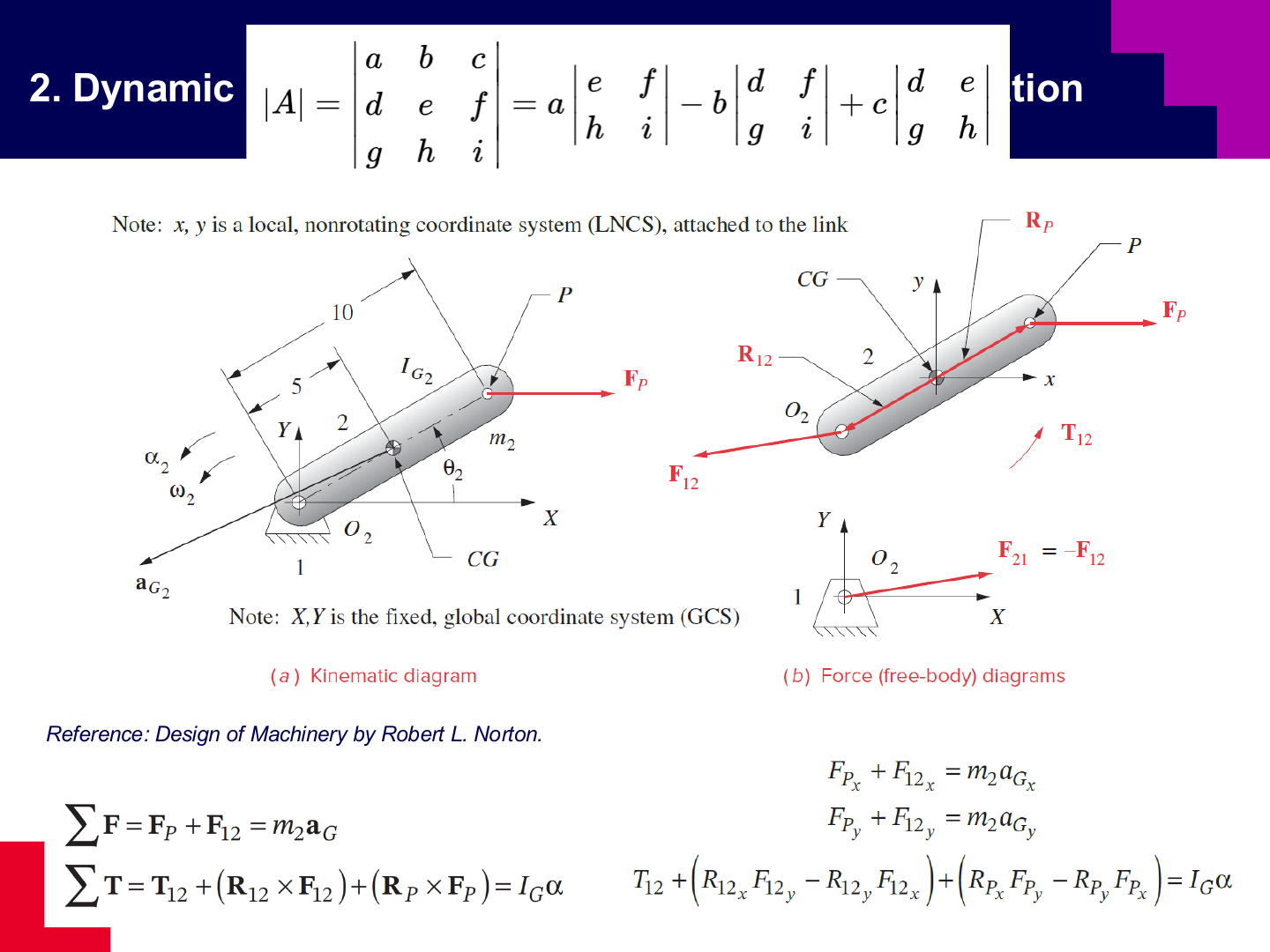
For link 2, the known force $\mathbf{F}_P$, unknown ground reaction $\mathbf{F}_{12}$ and unknown actuator torque $T_{12}$ produce the known linear and angular accelerations. Separating the vector equation into components gives $F_{Px}+F_{12x}=m_2a_{Gx}$ and $F_{Py}+F_{12y}=m_2a_{Gy}$, with the moment equation formed from position vectors measured from the centre of gravity.
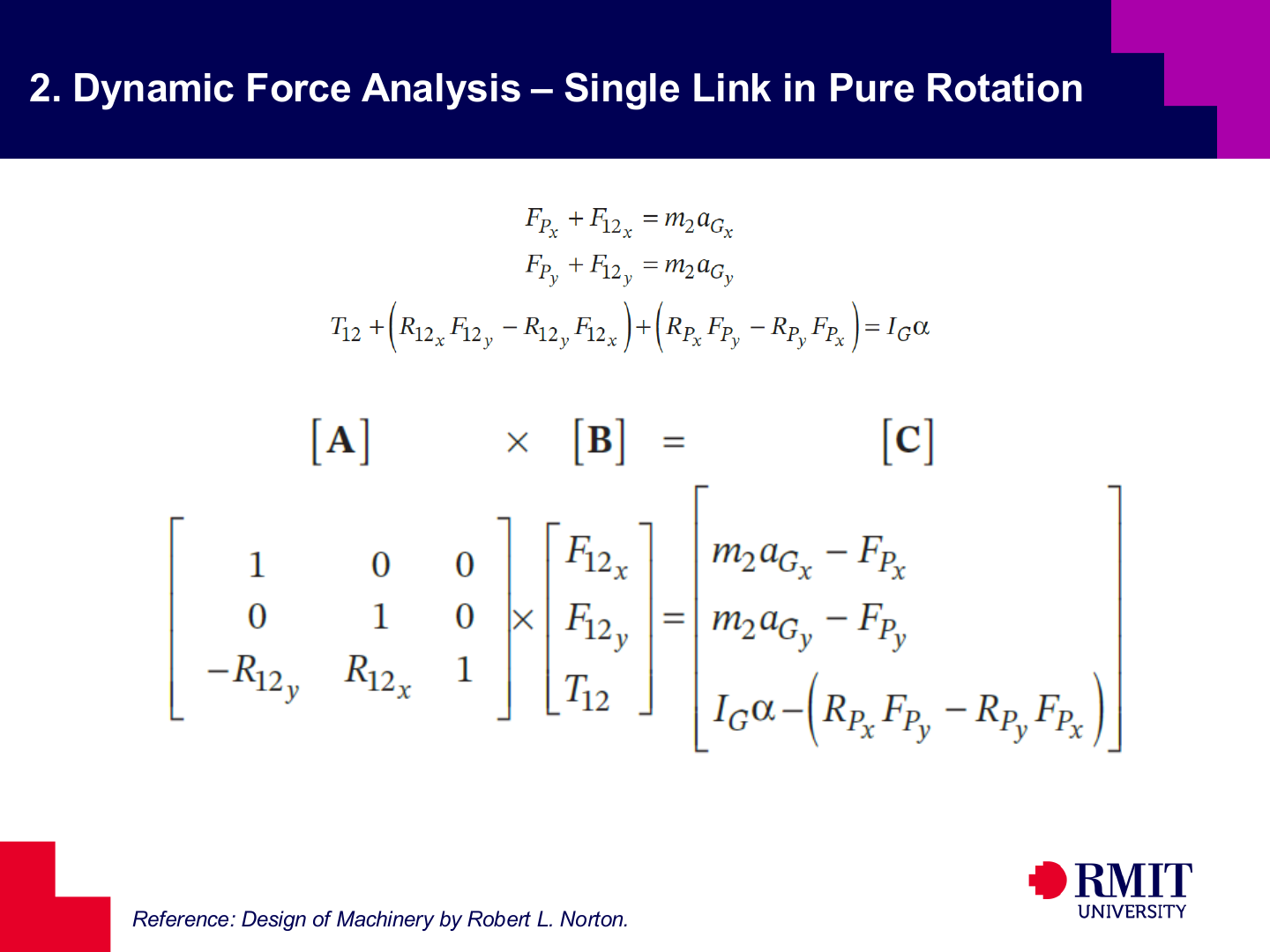
The three scalar equations can be written as $[A][B]=[C]$. The vector $[B]$ contains $F_{12x}$, $F_{12y}$ and $T_{12}$. Matrix $[A]$ contains the known moment arms, while $[C]$ contains the known inertia and applied-load terms.
The calculation gives force and torque at one position. To find the design loads, update the kinematic data and matrix values, then solve the system throughout the operating range.
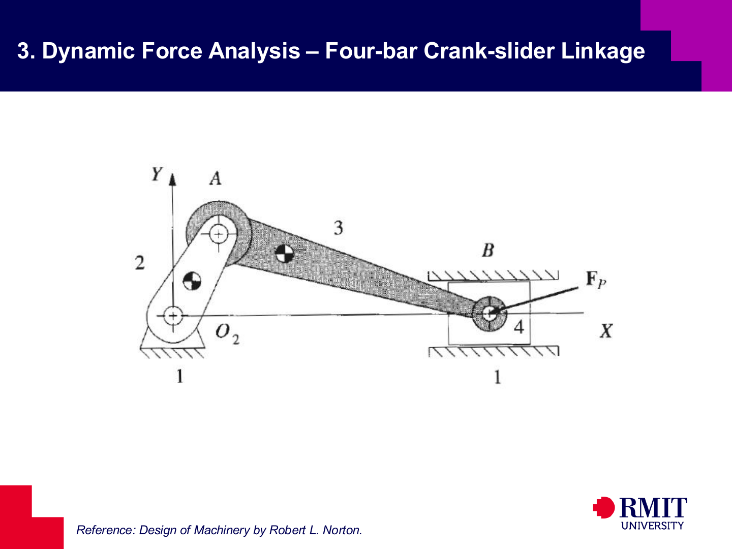
A four-bar crank-slider has ground link 1, crank 2, connecting link 3 and slider 4. Dynamic force analysis uses the position, velocity and acceleration results. These provide the mass-centre and angular accelerations on the right-hand side of the Newton-Euler equations. Separate the slider force $\mathbf{F}_P$ into global $x$- and $y$-components.
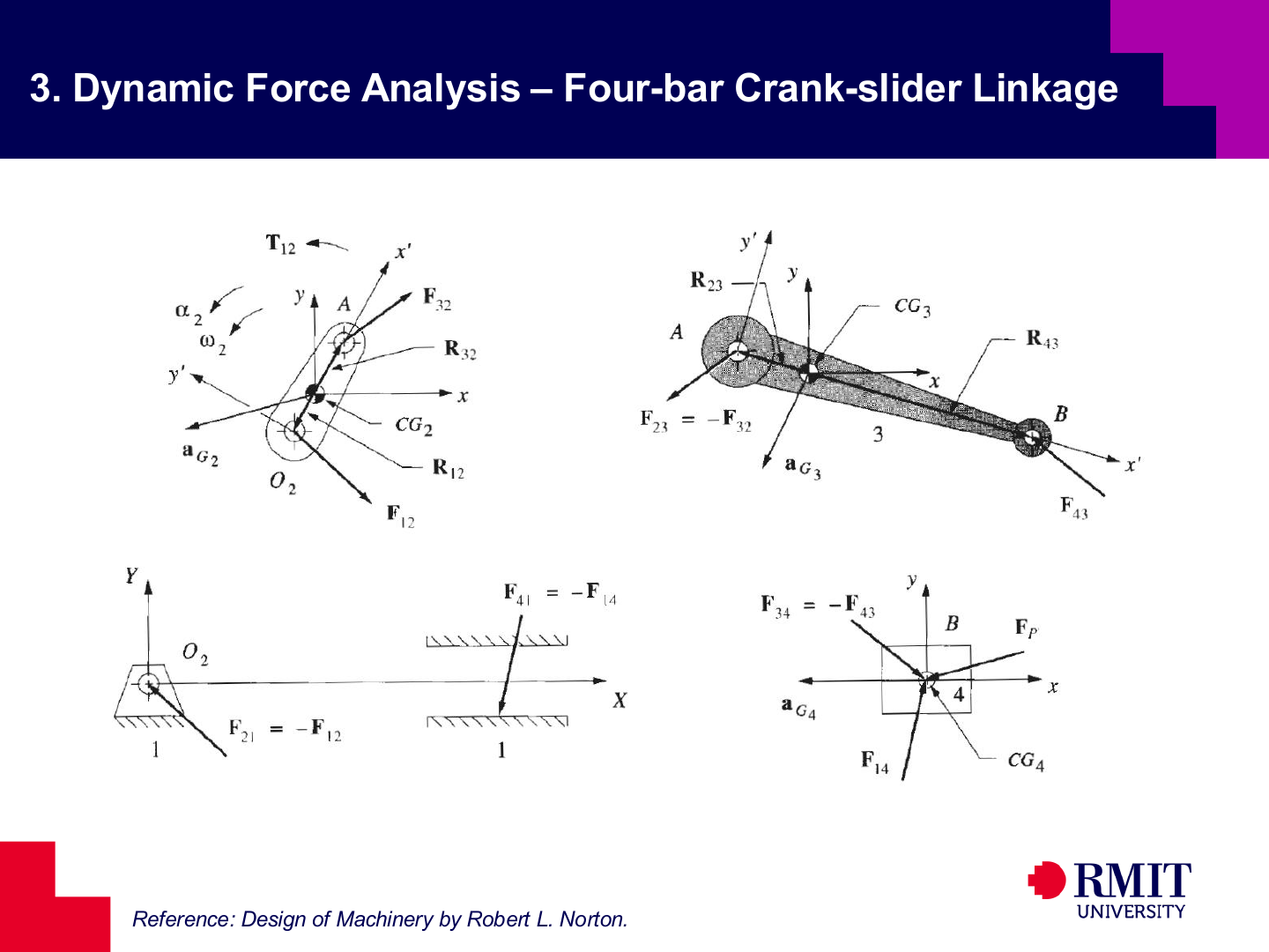
Draw one free-body diagram for each moving link. Forces at a shared pin are equal and opposite, so $\mathbf{F}_{23}=-\mathbf{F}_{32}$ and $\mathbf{F}_{34}=-\mathbf{F}_{43}$. The ground applies reaction $\mathbf{F}_{12}$ to the crank and reaction $\mathbf{F}_{14}$ to the slider. The unknown actuator torque $T_{12}$ acts on crank 2.
Use one non-rotating coordinate system for all force components and position vectors before combining the link equations. The local axes at the mass centres remain parallel to the global axes, although their origins move with the links.
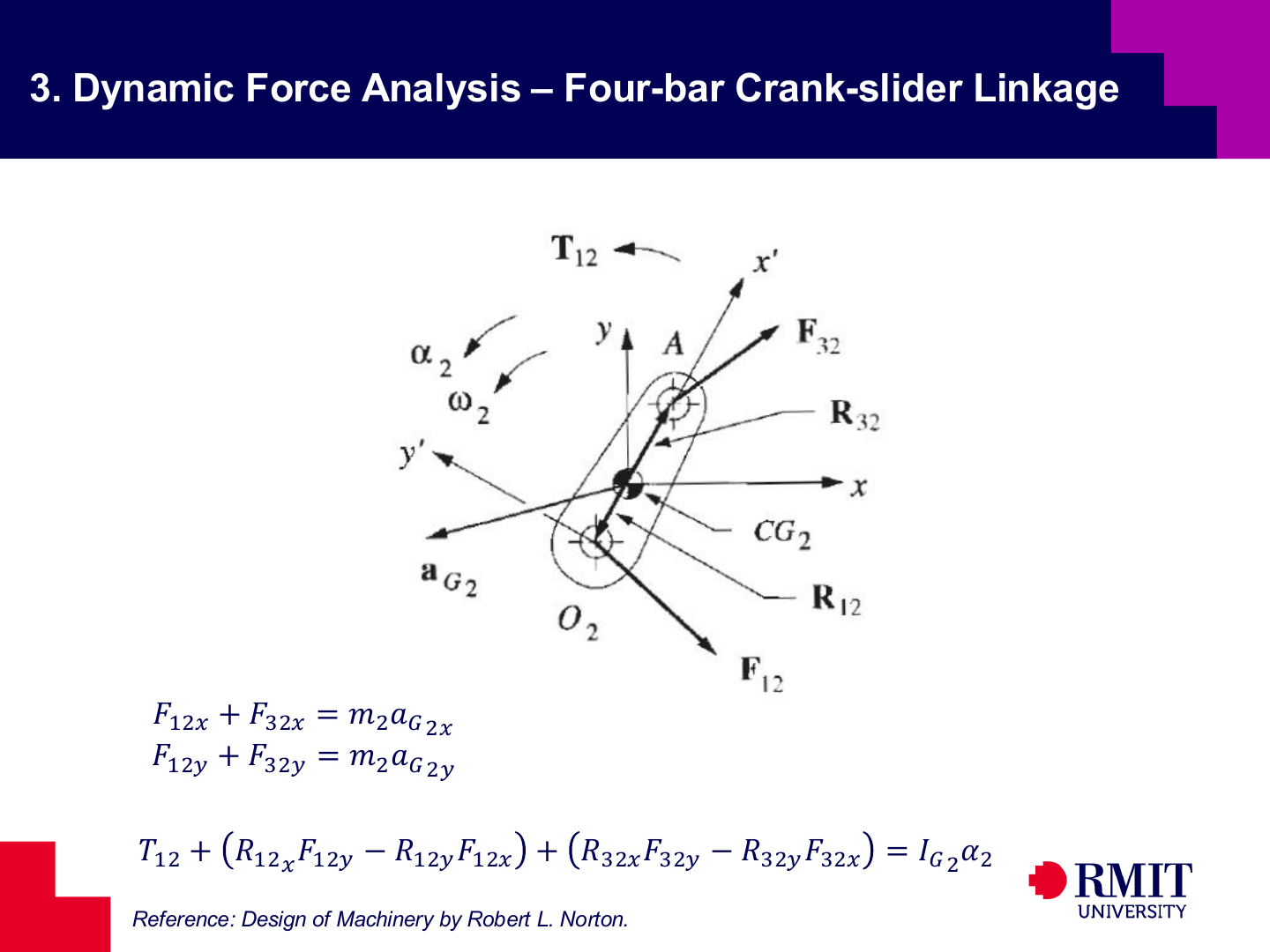
Crank 2 contributes two force equations and one moment equation.
The force balance in the $x$-direction is
\[F_{12x}+F_{32x}=m_2a_{G2x}.\]The force balance in the $y$-direction is
\[F_{12y}+F_{32y}=m_2a_{G2y}.\]Taking moments about $G_2$ gives
\[T_{12} +\left(R_{12x}F_{12y}-R_{12y}F_{12x}\right) +\left(R_{32x}F_{32y}-R_{32y}F_{32x}\right) =I_{G2}\alpha_2.\]The vectors $\mathbf{R}_{12}$ and $\mathbf{R}_{32}$ run from $G_2$ to the points where the corresponding forces act.
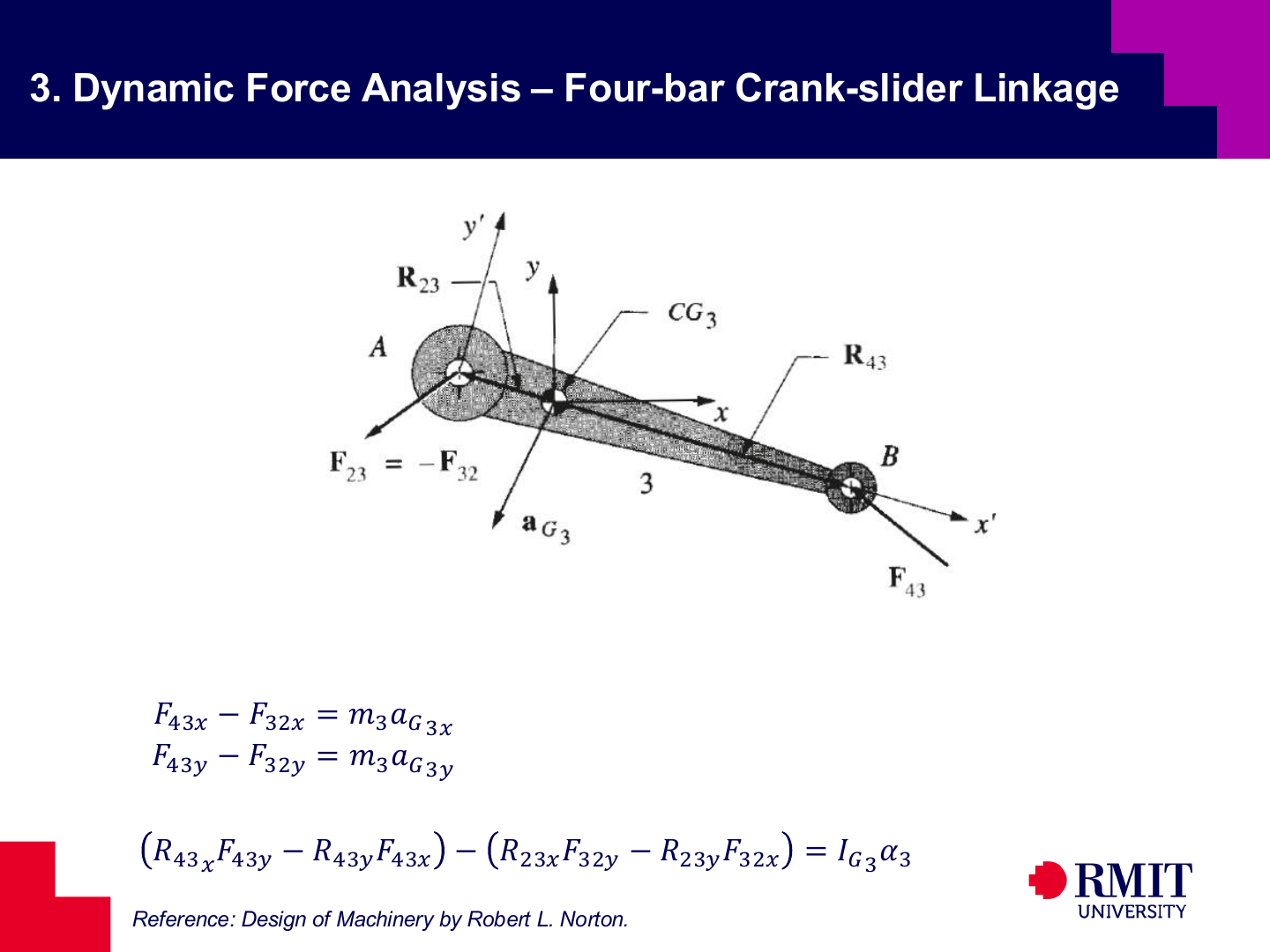
For connecting link 3, the force at $A$ is replaced by $\mathbf{F}_{23}=-\mathbf{F}_{32}$.
The force balance in the $x$-direction is
\[F_{43x}-F_{32x}=m_3a_{G3x}.\]The force balance in the $y$-direction is
\[F_{43y}-F_{32y}=m_3a_{G3y}.\]Taking moments about $G_3$ gives
\[\left(R_{43x}F_{43y}-R_{43y}F_{43x}\right) -\left(R_{23x}F_{32y}-R_{23y}F_{32x}\right) =I_{G3}\alpha_3.\]Using the same unknown pin-force components for links 2 and 3 applies Newton’s third law without creating duplicate unknowns.
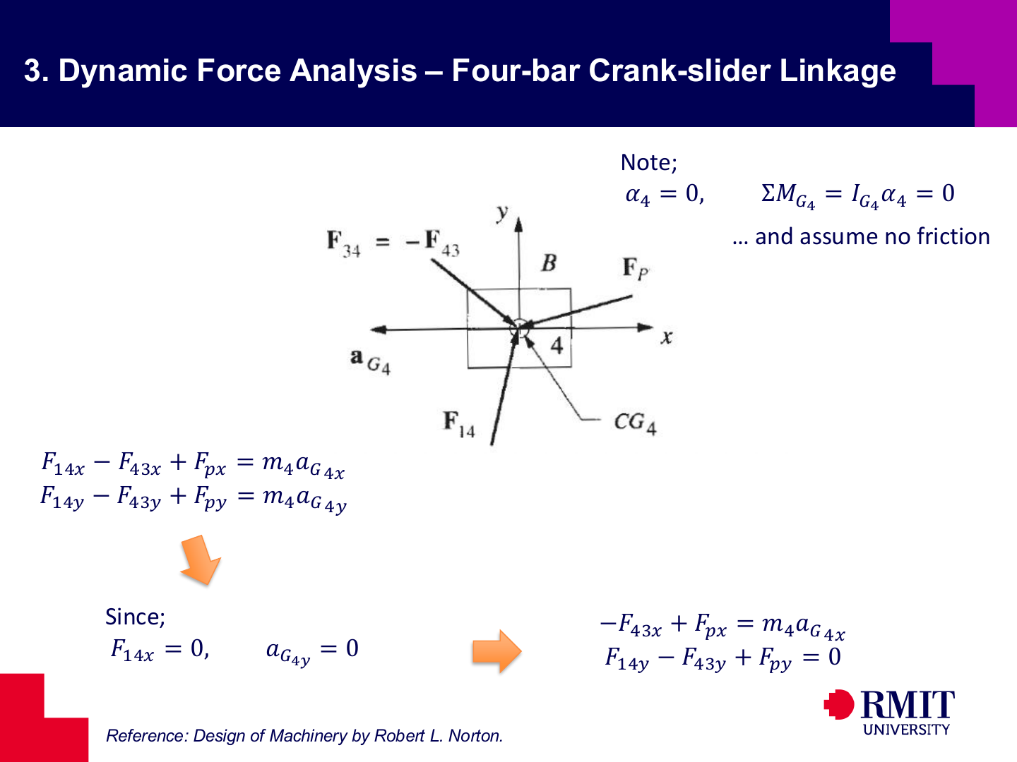
Slider 4 is acted on by $-\mathbf{F}_{43}$, the guide reaction $\mathbf{F}_{14}$, and the applied force $\mathbf{F}_P$.
The force balance in the $x$-direction is
\[F_{14x}-F_{43x}+F_{Px}=m_4a_{G4x}.\]The force balance in the $y$-direction is
\[F_{14y}-F_{43y}+F_{Py}=m_4a_{G4y}.\]For an ideal frictionless horizontal guide,
\[F_{14x}=0.\]The slider is also constrained against vertical acceleration:
\[a_{G4y}=0.\]The two force equations therefore reduce to
\[-F_{43x}+F_{Px}=m_4a_{G4x},\]and
\[F_{14y}-F_{43y}+F_{Py}=0.\]The slider does not rotate, so $\alpha_4=0$. The shown forces act through $G_4$, so its moment equation becomes $\sum M_{G4}=I_{G4}\alpha_4=0$ and adds no new unknown.
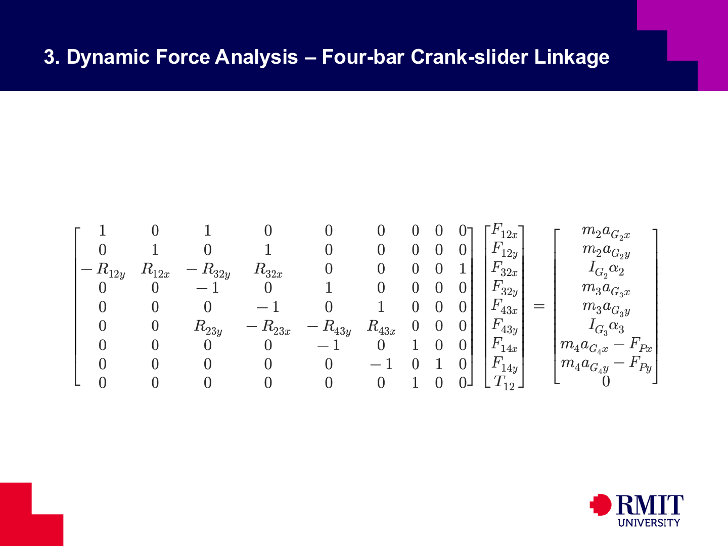
The crank-slider equations form a $9\times9$ linear system when the unknown vector is \([B]= \begin{bmatrix} F_{12x}&F_{12y}&F_{32x}&F_{32y}&F_{43x}&F_{43y}&F_{14x}&F_{14y}&T_{12} \end{bmatrix}^{T}.\) The first eight rows contain the force and moment equations for links 2, 3 and 4. The final row applies the guide constraint $F_{14x}=0$. The coefficient matrix contains known geometry, while the right-hand side contains known inertia and applied-force terms. Solving the system gives the joint forces, guide reaction and required actuator torque at one position.

[For Illustration Only]

[For Illustration Only]
The principal reference for the dynamic force-analysis examples is Robert L. Norton’s Design of Machinery.
Knowledge Check
Check your understanding of static and dynamic force analysis. Each question can be checked individually.
1. Why is dynamic force analysis often described as inverse dynamics?
2. When can static equilibrium be used for a moving mechanism?
3. What conditions must the forces on a two-force member satisfy?
4. How is the centre-of-gravity coordinate of a composite body determined?
5. Which equation moves a mass moment of inertia from the centre-of-mass axis to a parallel axis through $O$?
6. How many independent Newton-Euler equations does one unconstrained planar rigid link contribute?
7. How should a link's weight be treated in dynamic force analysis?
8. How does a local non-rotating coordinate system move?
9. How should the force at a shared pin between two links be represented in the simultaneous equations?
10. What are the nine unknowns in the four-bar crank-slider dynamic force-analysis matrix developed in the notes?
11. Why must dynamic force analysis normally be repeated at many mechanism positions?
12. How are the results of dynamic force analysis used in mechanical design?