Lecture 4: Bearings and Lubrication

[For Illustration Only]
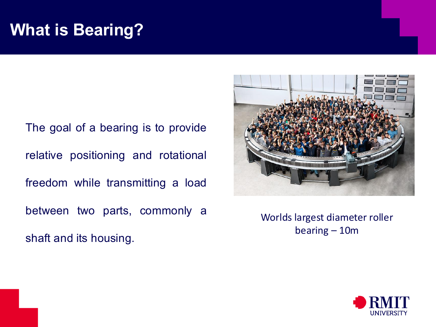
A bearing holds two components in the correct position while allowing movement between them. In a rotating machine, a bearing usually supports a shaft inside a housing. It transfers radial loads, axial loads, or both into the supporting structure. It must do this with acceptable friction, stiffness, accuracy and operating life.
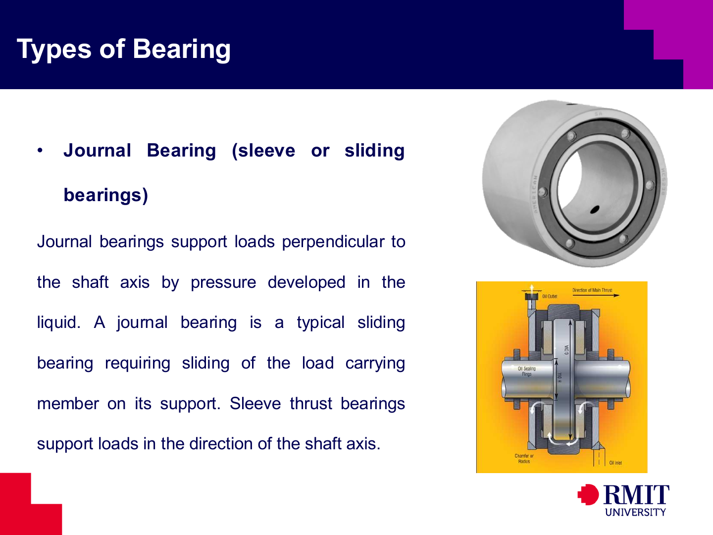
Journal bearings support a rotating shaft using sliding surfaces. A film of lubricant should separate these surfaces. A cylindrical journal bearing mainly carries radial load, while a thrust bearing carries axial load. Performance depends on surface speed, lubricant viscosity, clearance, alignment and the ability to remove heat.
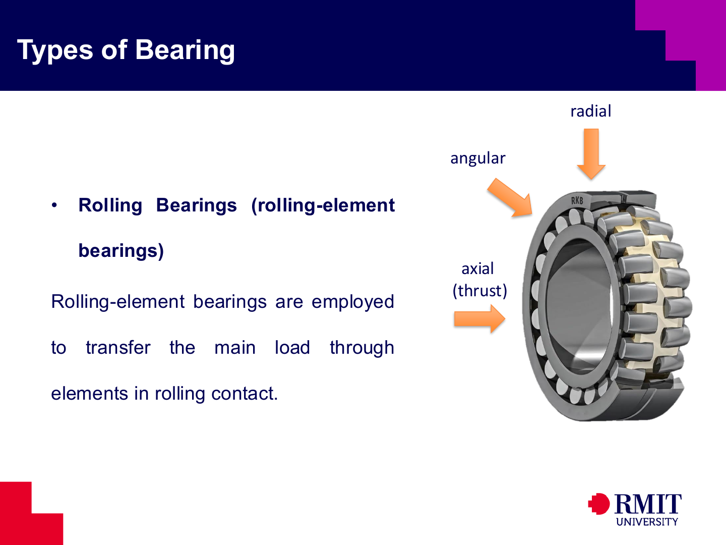
Rolling-element bearings use balls or rollers between inner and outer raceways. Rolling contact usually produces less friction during start-up than sliding contact. However, the contact stress can still be high. Repeated loading at the contact surfaces eventually limits the fatigue life of the bearing.
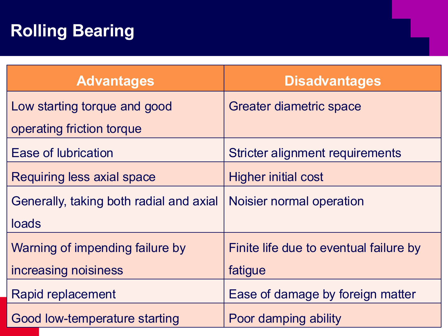
Rolling bearings have standard dimensions, relatively low friction and are usually easy to replace. Different designs can carry loads in several directions. However, they have a limited fatigue life. They can also be damaged by dirt, poor alignment and incorrect installation. They provide little damping, need extra space around the shaft and may become noisy as damage develops.
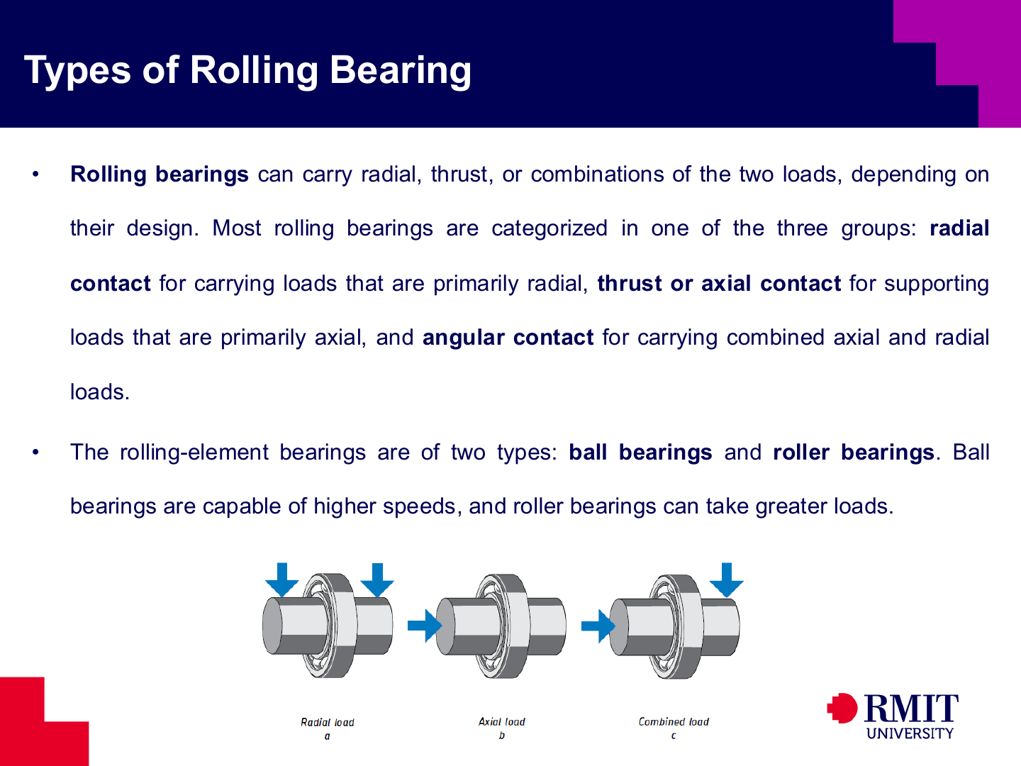
The shape of a bearing determines the directions in which it can carry load. Radial-contact bearings mainly support loads acting across the shaft, while thrust bearings support loads acting along the shaft. Angular-contact bearings can support both types of load. In an angular-contact bearing, the force passes through each rolling element at an angle to the radial plane, which is perpendicular to the shaft. This angle is called the contact angle. A larger contact angle generally allows the bearing to carry more axial load, but it can reduce the maximum operating speed. Ball bearings are generally suited to higher speeds, whereas roller bearings have a larger contact area and can usually carry heavier loads.
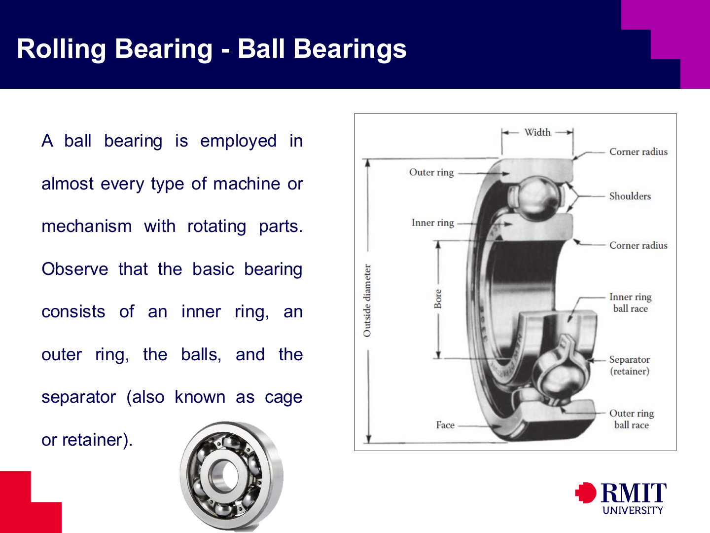
A ball bearing has an inner ring, an outer ring, raceways, balls and a cage. The raceways are the curved tracks on which the balls roll. The rings transfer load between the shaft and the housing. The cage keeps the balls evenly spaced and stops neighbouring balls from rubbing against each other.
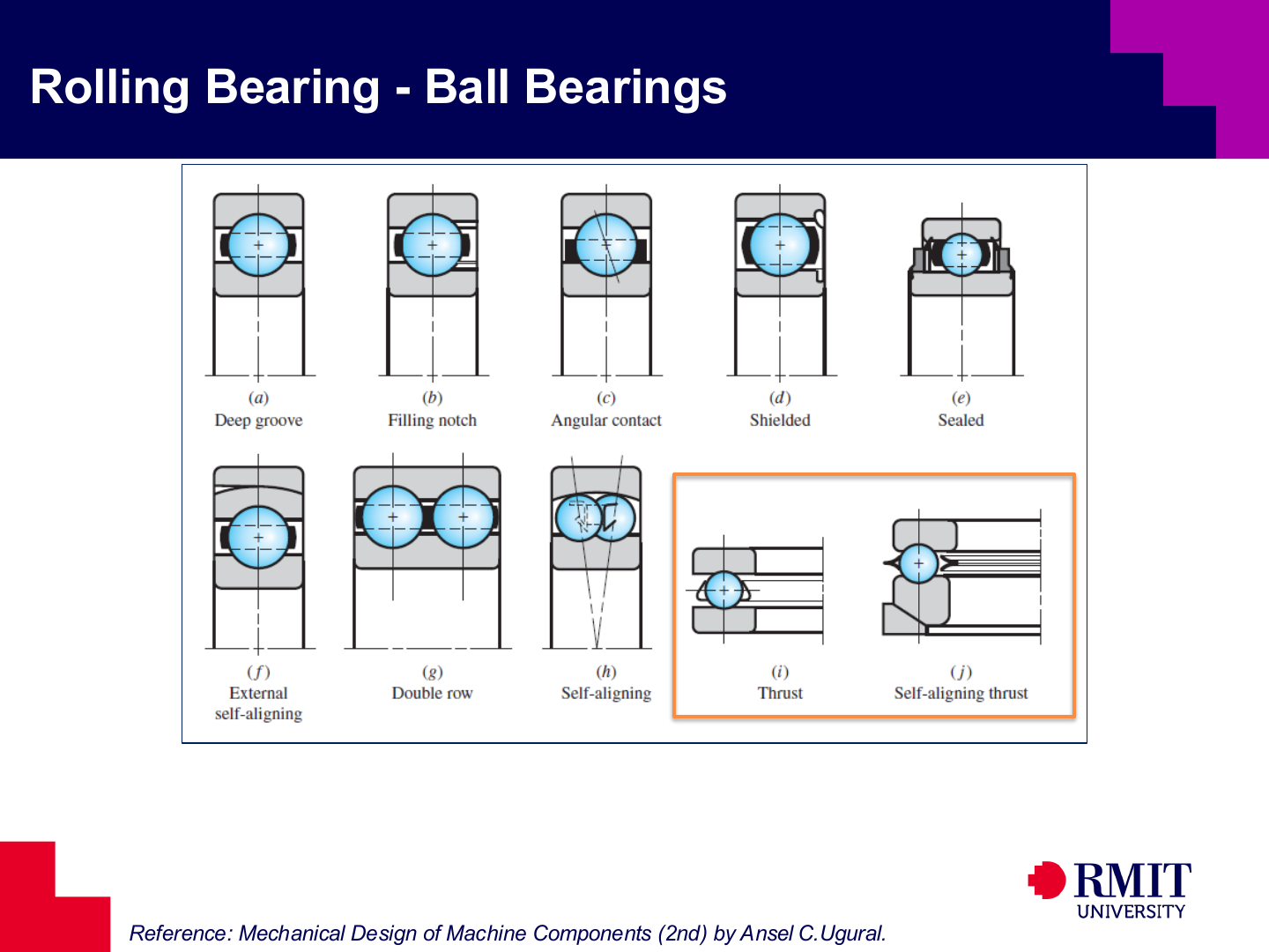
Deep-groove bearings mainly carry radial load, but they can also carry a moderate axial load. Angular-contact bearings carry both radial and axial loads. A larger contact angle generally increases axial-load capacity, but it also changes the speed and stiffness of the bearing. A single row mainly carries axial load in one direction. Two bearings are therefore often mounted in opposite directions when the axial load can reverse. Self-aligning bearings allow some angular misalignment, while double-row bearings provide greater load capacity. Thrust bearings are designed for axial load. Shields and seals help keep dirt out and lubricant in.
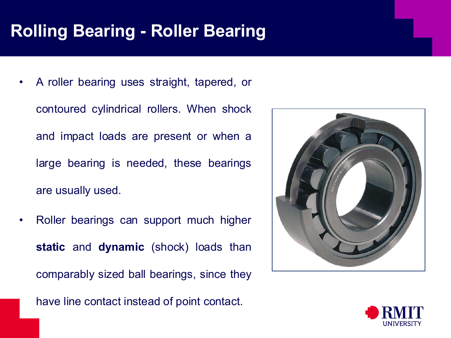
A roller contacts the raceway along a narrow line, while a ball is often treated as making contact at a point. The larger contact area of a roller reduces contact stress for the same load. Roller bearings can therefore carry greater static, dynamic and shock loads. However, their maximum speed is generally lower than that of ball bearings.
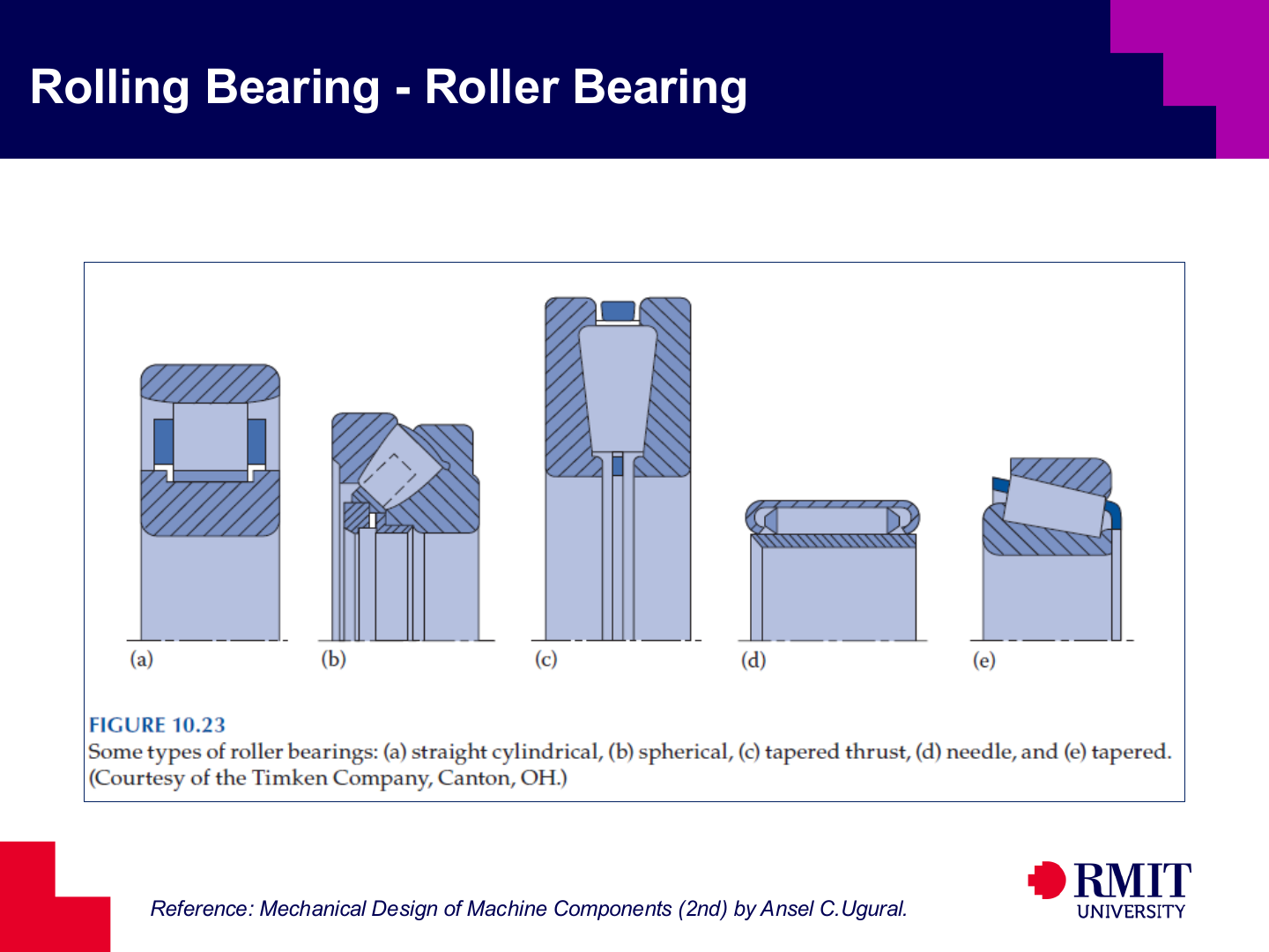
Cylindrical roller bearings have a high radial-load capacity. Spherical roller bearings can operate with some misalignment. Tapered roller bearings carry both radial and axial loads. Needle roller bearings carry a large radial load in a small radial space. Roller-thrust bearings carry axial load. The selected roller shape affects load capacity, alignment, friction and speed.
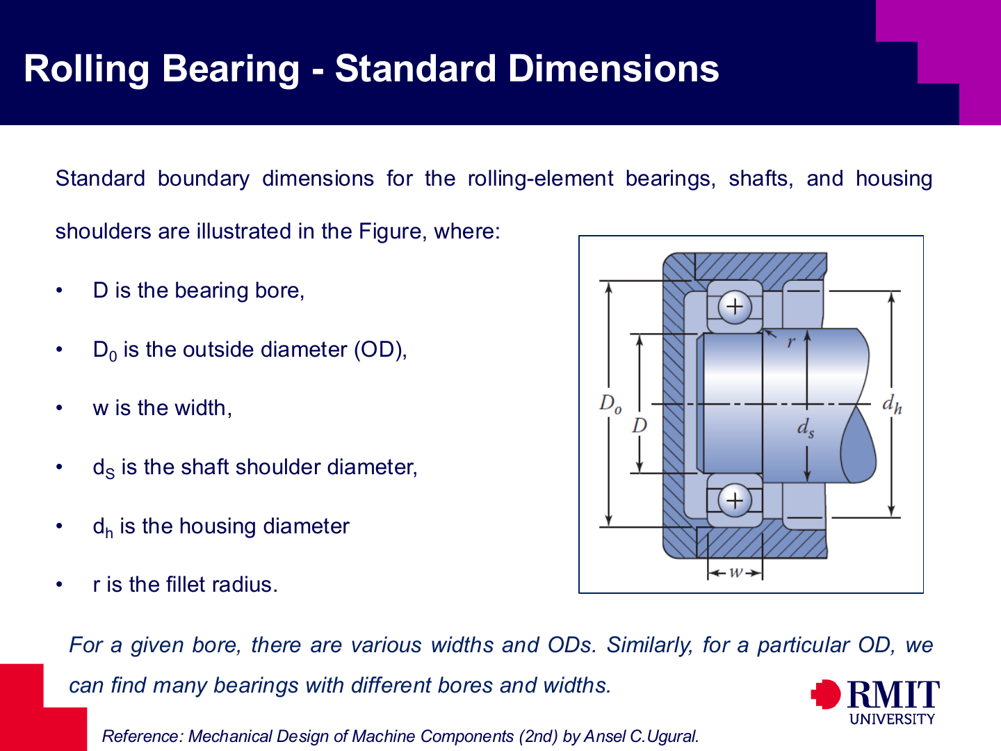
Standard bearing dimensions make catalogue selection and installation easier. The bore $D$, outside diameter $D_o$, width $w$, shoulder diameters and allowable fillet radius must fit the shaft and housing. A fillet is the rounded corner where the shaft diameter changes. If the shaft fillet is too large, the bearing ring cannot sit correctly against the shaft shoulder.
Bearings with the same bore can belong to different dimension series. For example, an 03-series bearing is normally wider or has a larger outside diameter than the matching 02-series bearing. It therefore usually has a higher dynamic load rating. Always identify the series before reading $C_{10}$ or $C_0$ from the stated catalogue. The bore diameter alone does not determine bearing capacity.
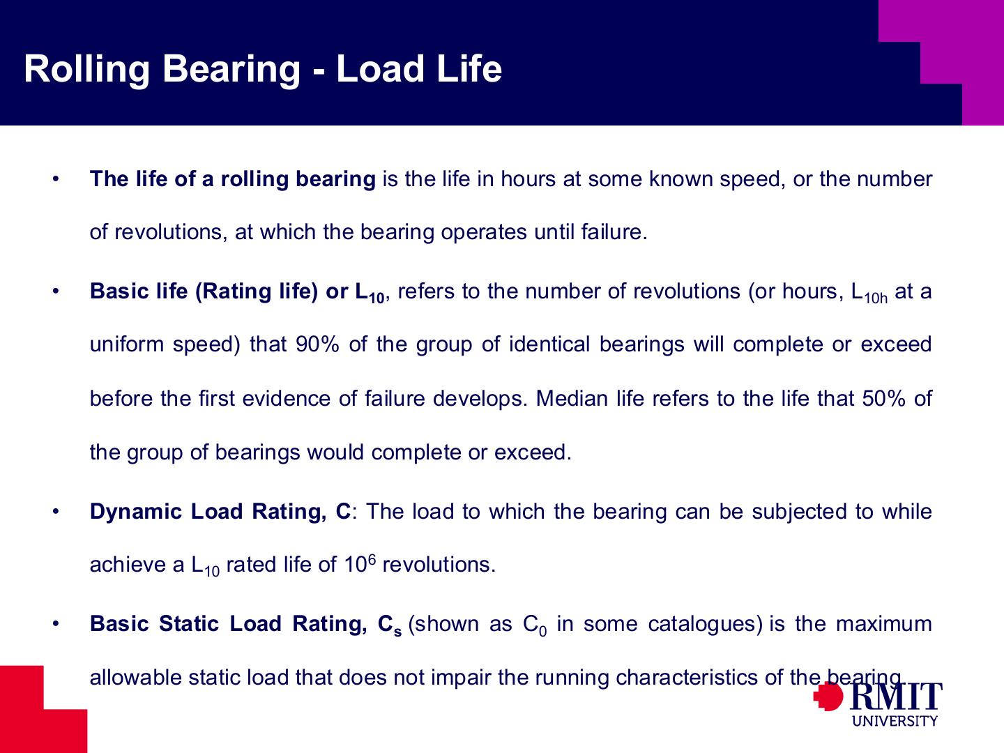
Bearing fatigue life is statistical because identical bearings do not all fail after the same number of cycles. The basic rating life $L_{10}$ is the life reached or exceeded by 90% of a large group of identical bearings. The median life $L_{50}$ is reached or exceeded by 50% of the group. There is no single conversion from $L_{10}$ to $L_{50}$. The conversion depends on the chosen life distribution or a given life-adjustment factor.
The basic dynamic load rating is written as $C$ in the life equation and as $C_{10}$ in Table 11-2. It gives an $L_{10}$ life of $10^6$ revolutions under the catalogue test conditions, so $C=C_{10}$. The basic static rating is written as $C_s$ in the combined-load factor table and as $C_0$ in Table 11-2, so $C_s=C_0$. It is based on a specified amount of permanent deformation. Use the static rating to select some combined-load factors and to check stationary or very slow bearings. Use the dynamic rating in the fatigue-life equation. These two ratings cannot be used in place of each other.
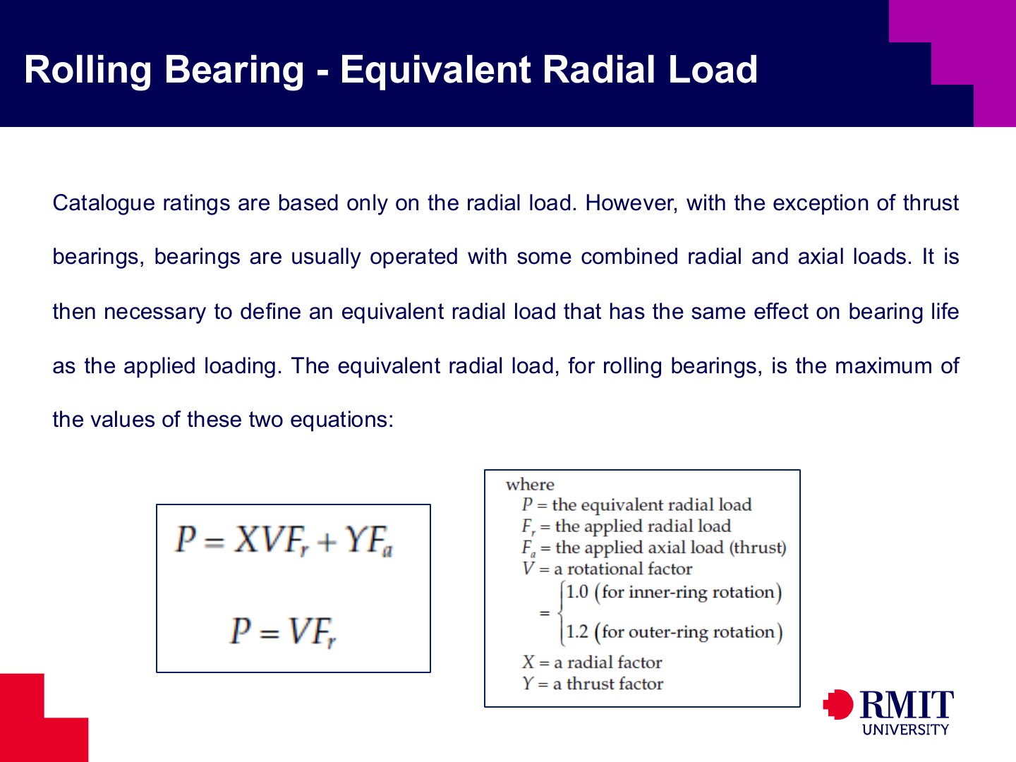
Catalogue life ratings use an equivalent radial load $P$. This single calculated load has the same fatigue effect as the actual radial and axial loads acting together. For a radial bearing, the general equation is
\[P=XVF_r+YF_a\]and the radial-only expression is
\[P=VF_r,\]where $F_r$ is radial load, $F_a$ is axial load, $V$ is a rotation factor, and $X$ and $Y$ are catalogue factors. The catalogue normally requires this comparison:
\[\frac{F_a}{VF_r}\mathrel{\lessgtr}e.\]For a deep-groove bearing, first calculate $F_a/C_s$, where $C_s=C_0$. Use this value to find or interpolate the limit $e$ and the factor $Y$. If $F_a/(VF_r)\leq e$, the axial load is small enough to use the radial-load equation. In this case, $X=1$ and $Y=0$ are normally used. If $F_a/(VF_r)>e$, use the combined-load values of $X$ and $Y$. For an angular-contact bearing, select $e$, $X$ and $Y$ from the row for its contact angle. For example, the stated catalogue gives $e=0.95$ for a single-row bearing with a $35^\circ$ contact angle. Above this limit, it gives $X=0.37$ and $Y=0.66$.
In the stated catalogue, $V=1.0$ when the inner ring rotates relative to a fixed load. Use $V=1.2$ when the outer ring rotates. For a cylindrical roller bearing with no axial load, $X=1$ and $Y=0$. The equation then becomes $P=VF_r$. Factor values can differ between catalogues, so always check the catalogue being used.
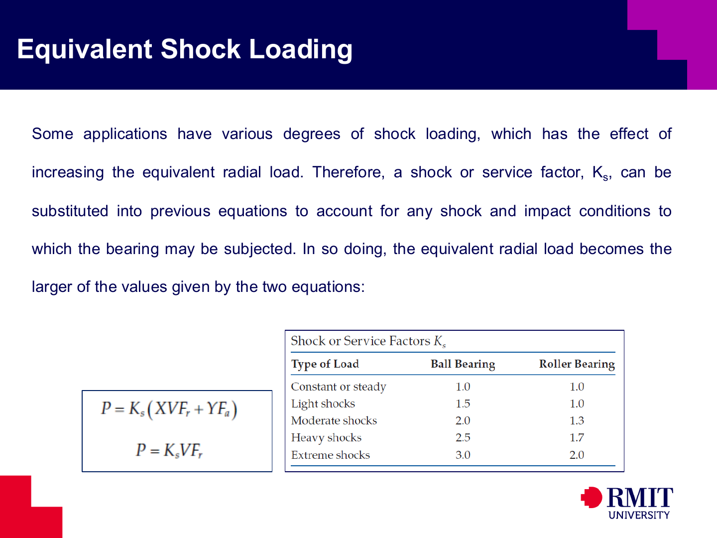
Shock, impact and changing operating conditions can make a load more damaging. The service factor $K_s$ allows for these effects by increasing the equivalent load before calculating bearing life. For example,
\[P=K_s\left(XVF_r+YF_a\right).\]For a radial-only case with $X=1$ and $Y=0$, this reduces to
\[P=K_sVF_r.\]The example table gives $K_s=1.0$ for steady loading. For heavy shock, it gives $K_s=2.5$ for a ball bearing and $K_s=1.7$ for a roller bearing. For light shock, it gives $K_s=1.5$ for a ball bearing and $K_s=1.0$ for a roller bearing. These values come from test data and apply only to the stated table. Use values from the manufacturer when available. Bearing life depends on a high power of $C/P$, so even a small increase in $P$ can greatly reduce the predicted life. Apply $K_s$ once when calculating $P$. Do not apply it again to the calculated life.
Small differences from manufacturing and rolling-contact fatigue mean that identical bearings do not have one fixed failure time. Bearing selection therefore uses catalogue ratings with a stated reliability. Static capacity must also be checked when a stationary or slowly moving bearing carries a heavy load. A heavy static load can leave permanent dents in a raceway and affect later operation, even when fatigue cycles are not present.
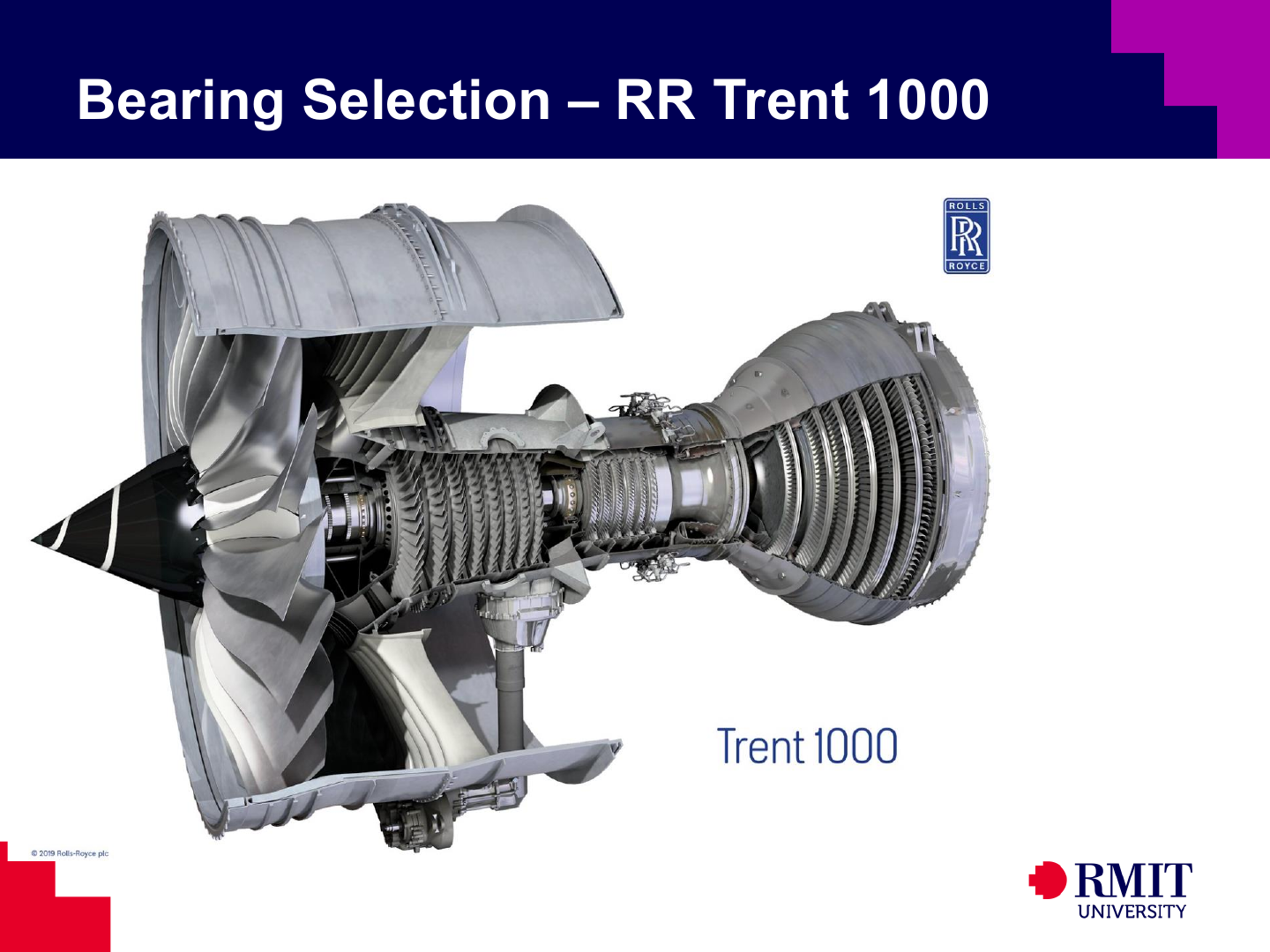
An aircraft gas turbine shows why bearing selection is important in a fast and highly reliable machine. Its bearings support several rotating shafts. They carry forces caused by airflow, rotation and aircraft manoeuvres while operating at high temperatures with demanding lubrication conditions. Load capacity alone is not enough. The design must also consider speed, cooling, reliability, stiffness and the control of damage if a failure occurs.
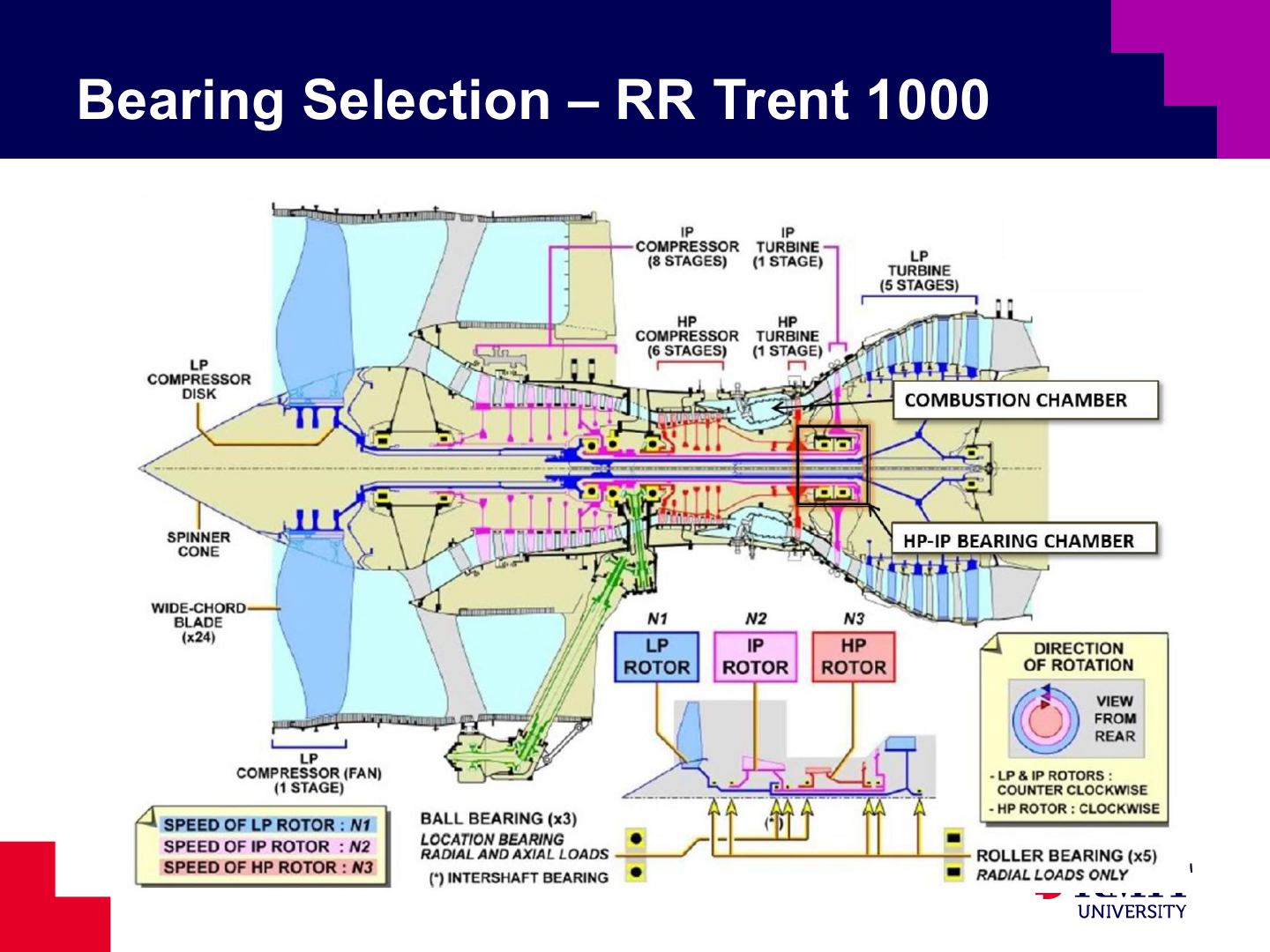
Multi-spool engines have shafts inside other shafts, and each shaft can rotate at a different speed. Ball bearings can hold a shaft in both the radial and axial directions. Roller bearings often provide radial support while allowing the shaft to expand along its length as it becomes hot. The type and position of each bearing therefore affect rotor alignment and the path of loads through the engine.
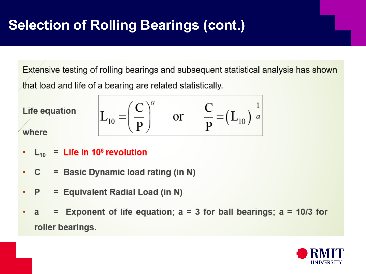
Basic rating life in millions of revolutions is
\[L_{10}=\left(\frac{C}{P}\right)^a,\]where $C$ is the dynamic load rating, $P$ is the equivalent dynamic load and $a$ is the life exponent. Use $a=3$ for ball bearings and $a=10/3$ for roller bearings. Both $C$ and $P$ must use the same force unit because they form the ratio $C/P$. The answer is in millions of revolutions. For example, $L_{10}=20$ means $20\times10^6$ revolutions. This equation assumes a constant equivalent load. If the load changes during operation, first calculate an equivalent load for the operating cycle.
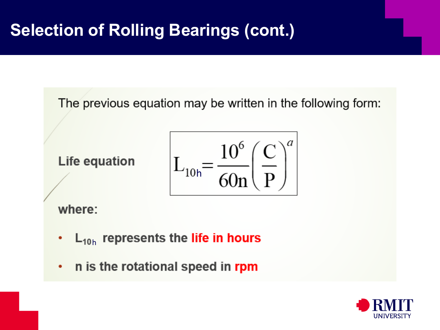
At a constant speed $n$ in revolutions per minute, rating life in hours is
\[L_{10h}=\frac{10^6}{60n}\left(\frac{C}{P}\right)^a.\]The factor $10^6/(60n)$ changes millions of revolutions into hours because the bearing completes $60n$ revolutions each hour. For a correct calculation, select $C$ for the correct bearing series, calculate $P$ using the load and service factors, and select $a$ for the type of rolling element. The equation assumes that the ratings, equivalent load, speed, lubrication and other operating conditions remain valid.
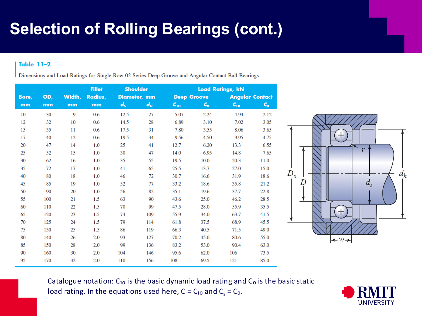
A catalogue row gives both installation dimensions and load ratings. The bore, outside diameter, width, corner radius and shoulder diameters show whether the bearing will fit. The dynamic and static ratings show whether it can meet the life and deformation requirements. Deep-groove and angular-contact bearings of the same size can have different ratings. The same is true for 02- and 03-series bearings with the same bore. Before copying a rating into a calculation, check the bore, dimension series, rolling-element type and contact arrangement.
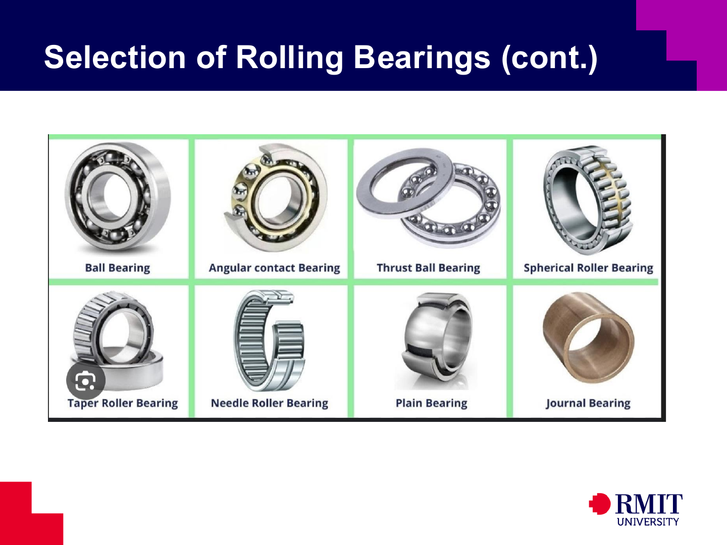
Each bearing type suits different load, speed, alignment, space and friction requirements. These types include ball, angular-contact, thrust, spherical-roller, tapered-roller, needle, plain and journal bearings. Begin selection by identifying the direction of the load and the required motion. Then remove any types that do not meet the space, mounting, lubrication, accuracy or environmental requirements.
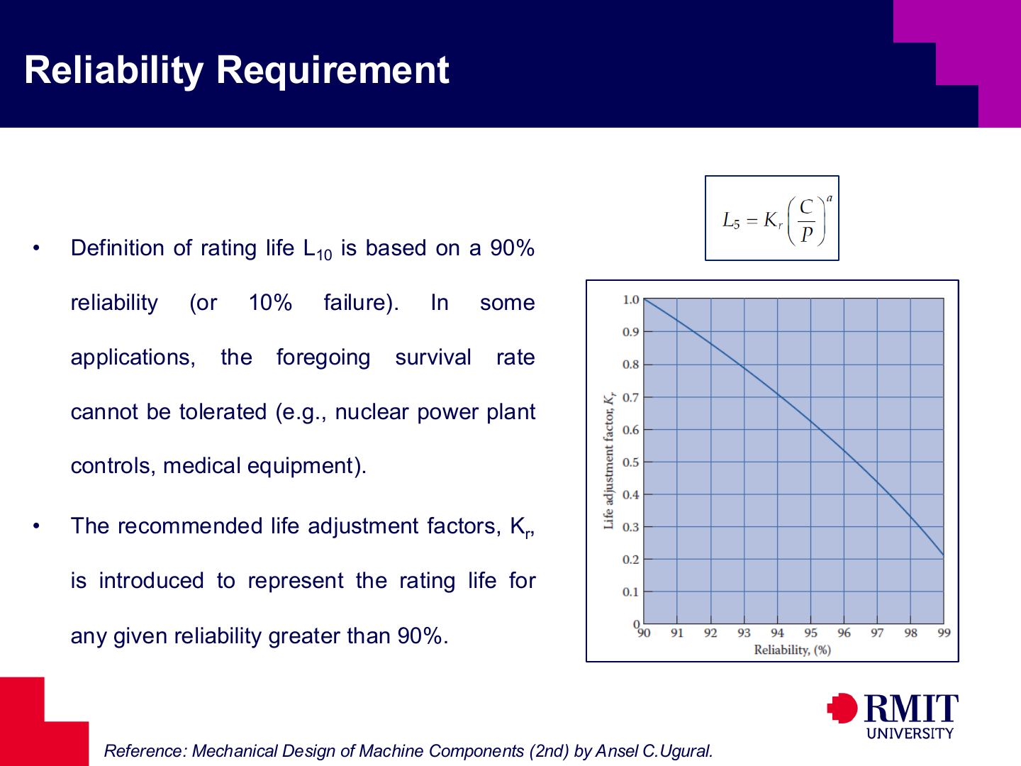
Standard $L_{10}$ life has 90% reliability. This means that 10% of a large group of identical bearings may show fatigue failure before reaching this life. When higher reliability is required, a reliability factor $K_r<1$ reduces the stated life:
\[L_R=K_r\left(\frac{C}{P}\right)^a.\]Here $L_R$ is in millions of revolutions. At constant speed, the corresponding life in hours is
\[L_{Rh}=K_r\frac{10^6}{60n}\left(\frac{C}{P}\right)^a.\]Reliability $R$ and failure probability $p_f$ add to one, so $R=1-p_f$. A permitted failure probability of 2% therefore means 98% reliability. This life is commonly called $L_2$. For the stated reliability curve, $R=98\%$ gives approximately $K_r=0.32$. Apply this factor after raising the ratio $C/P$ to the correct exponent. Higher reliability requires a larger $C/P$ ratio or a shorter stated service life.
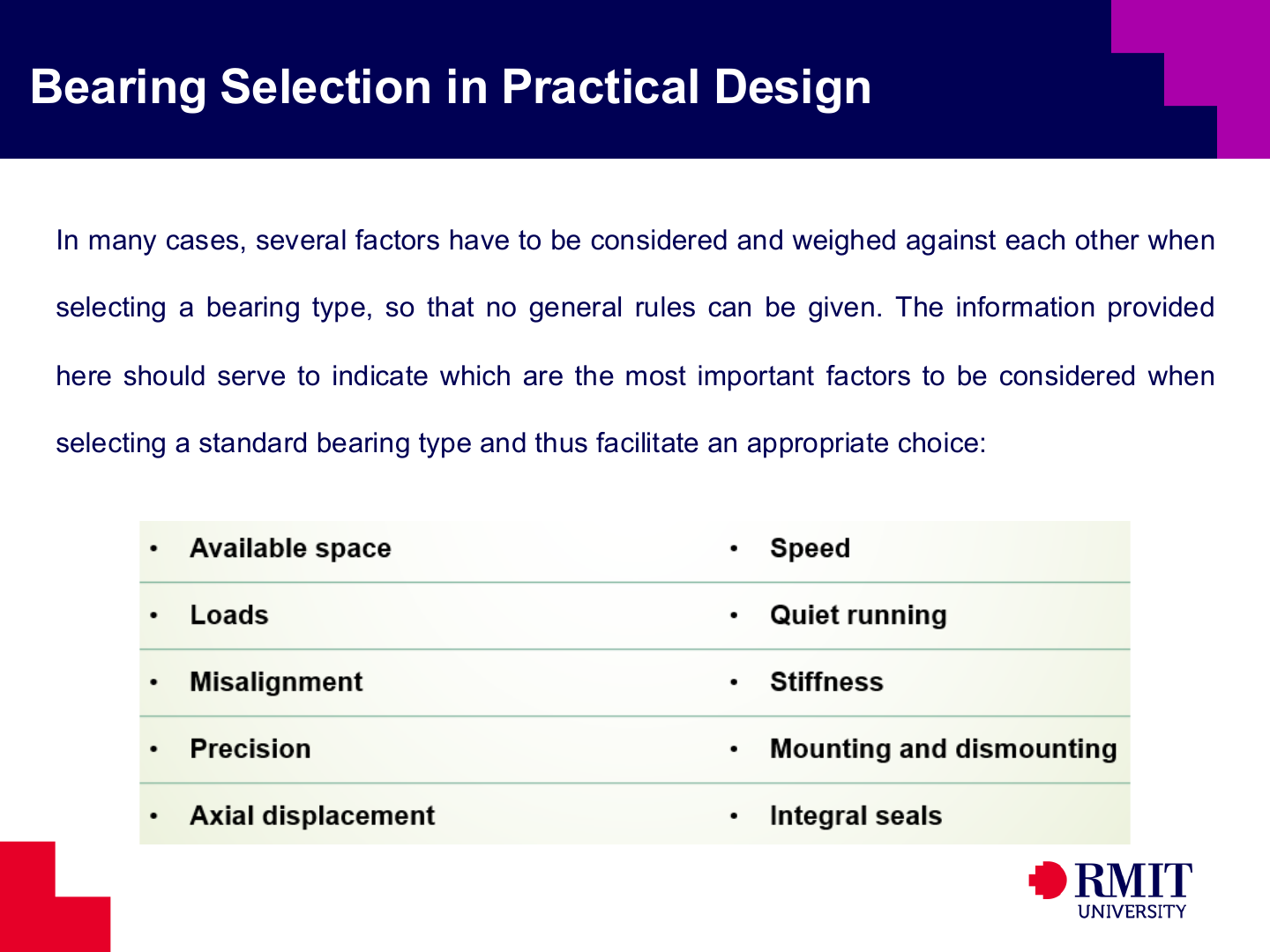
Practical bearing selection must consider available space, radial and axial loads, speed, misalignment, accuracy, stiffness, noise, axial movement, mounting and sealing. Improving one requirement can make another worse. For example, a stiff bearing arrangement may not allow enough thermal expansion. A self-aligning bearing allows more misalignment, but may locate the shaft less accurately than a rigid bearing arrangement.
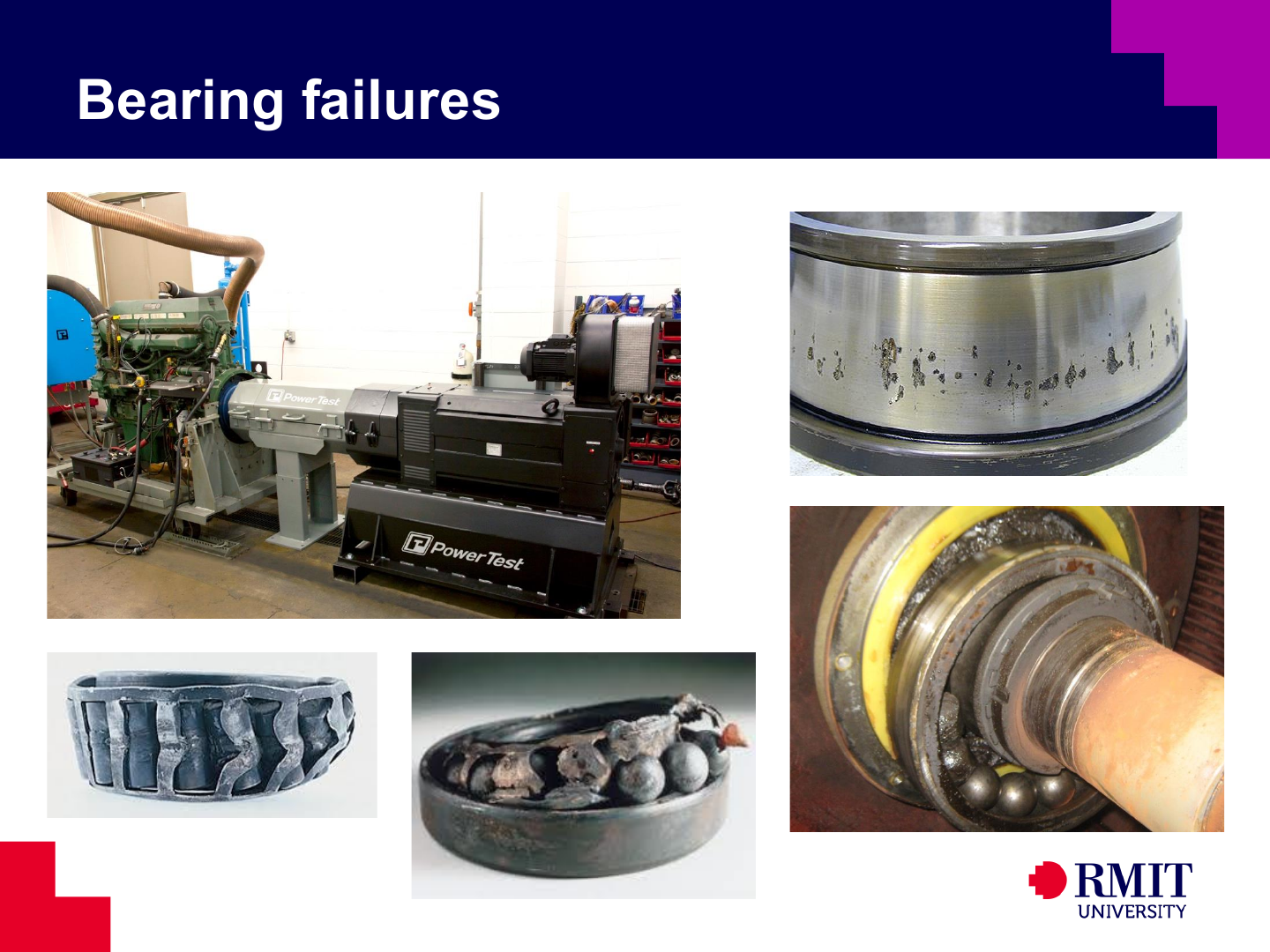
Bearing damage can result from rolling-contact fatigue, dirt, too little or too much lubricant, corrosion, electric current, overload, incorrect fits, misalignment or poor installation. Similar surface damage can have different causes. To identify the cause, examine the damage together with information about the load, temperature, vibration, lubricant and mounting.


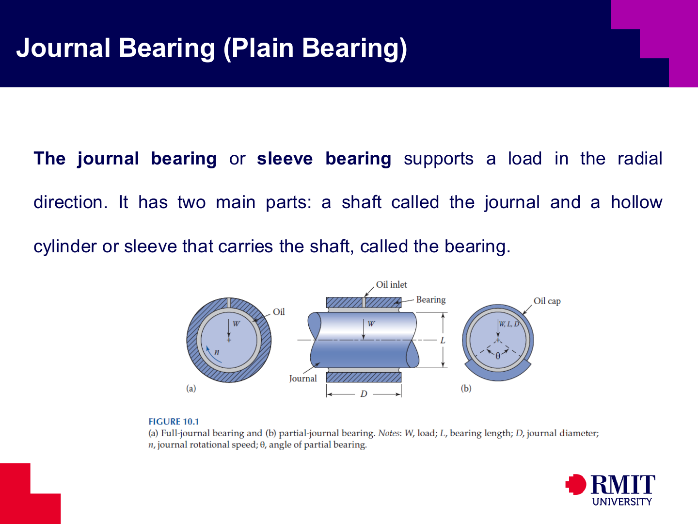
A journal is the part of a shaft supported by a plain bearing. A sleeve surrounds the journal with a small radial clearance. Lubricant enters the gap to reduce friction and prevent the two surfaces from touching directly. A full bearing surrounds the complete journal, while a partial bearing supports only part of it.
In journal-bearing design, the designer selects the lubricant viscosity, bearing diameter, bearing length, clearance and allowable load. These choices affect friction, temperature rise, lubricant flow and minimum film thickness. The design must keep each of these results within safe limits under all expected operating conditions.
Viscosity describes how strongly a fluid resists flow and shearing. A lubricant with suitable viscosity can form a film that supports the load, but it also creates frictional heat. Viscosity normally decreases as temperature rises. A bearing that becomes too hot can therefore lose film thickness and move towards mixed lubrication. However, a lubricant with very high viscosity can increase fluid friction, especially during a cold start. The important value is the viscosity at the operating temperature, not only the lubricant grade at a reference temperature.
Bearing pressure is commonly based on projected area,
\[p=\frac{W}{LD},\]where $W$ is radial load, $L$ is bearing length, and $D$ is journal diameter. Lower projected pressure generally improves film formation and reduces surface stress, at the cost of a larger bearing.
The ratio $L/D$ affects load distribution, lubricant flow, heat removal and sensitivity to misalignment. A short bearing can more easily allow for shaft bending and angular error. A longer bearing has a larger projected area, but it needs better alignment to prevent a high load at its edge.
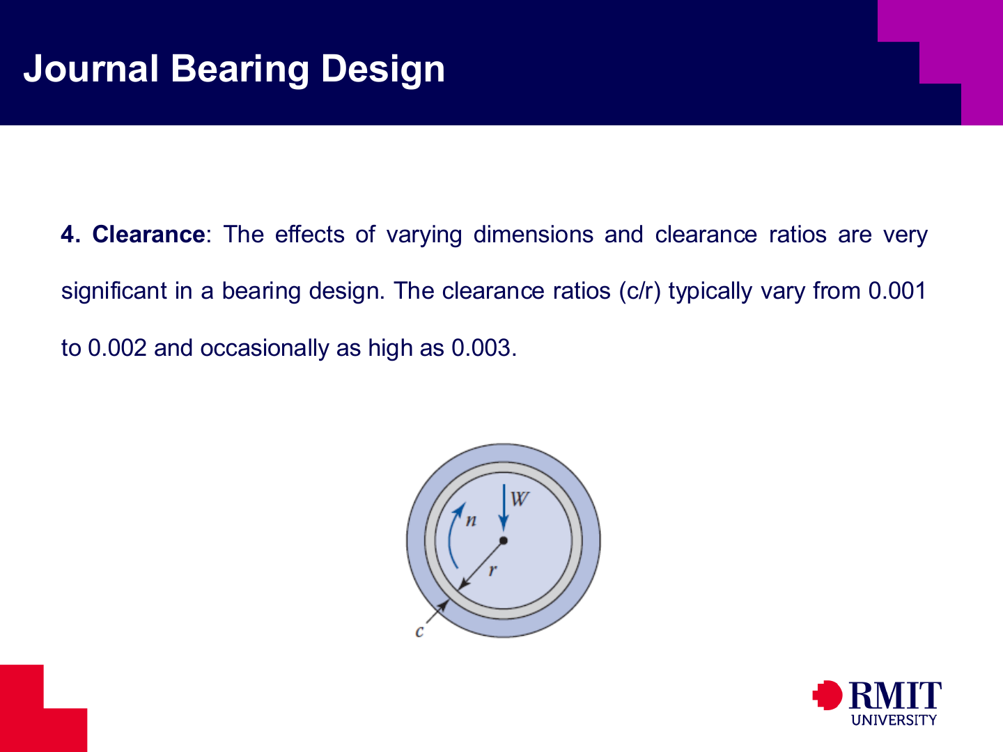
Radial clearance $c$ provides space for assembly, lubricant flow and the formation of a hydrodynamic pressure wedge. The ratio $c/r$ has no units because both $c$ and $r$ are lengths. Too little clearance can cause surface contact and overheating. Too much clearance reduces film pressure and makes the shaft position less accurate.
In hydrodynamic lubrication, a pressurised fluid film completely separates the two surfaces. Shaft rotation pulls lubricant into a gap that becomes narrower in the direction of motion. This narrowing gap creates pressure in the lubricant, and the pressure supports the load. Under load, the journal centre moves away from the bearing centre. This off-centre position forms the narrowing gap, called a converging wedge. Hydrodynamic lubrication needs enough relative speed, suitable viscosity and clearance, and a continuous lubricant supply.
In mixed lubrication, the fluid film supports part of the load, but some asperities still touch. Asperities are the microscopic high points on surfaces that appear smooth. In boundary lubrication, the film is too thin to separate the surfaces. Friction and wear then depend strongly on the surface materials and lubricant additives. Start-up, shutdown, low speed, excessive load and high temperature can move a bearing from hydrodynamic lubrication into mixed or boundary lubrication.


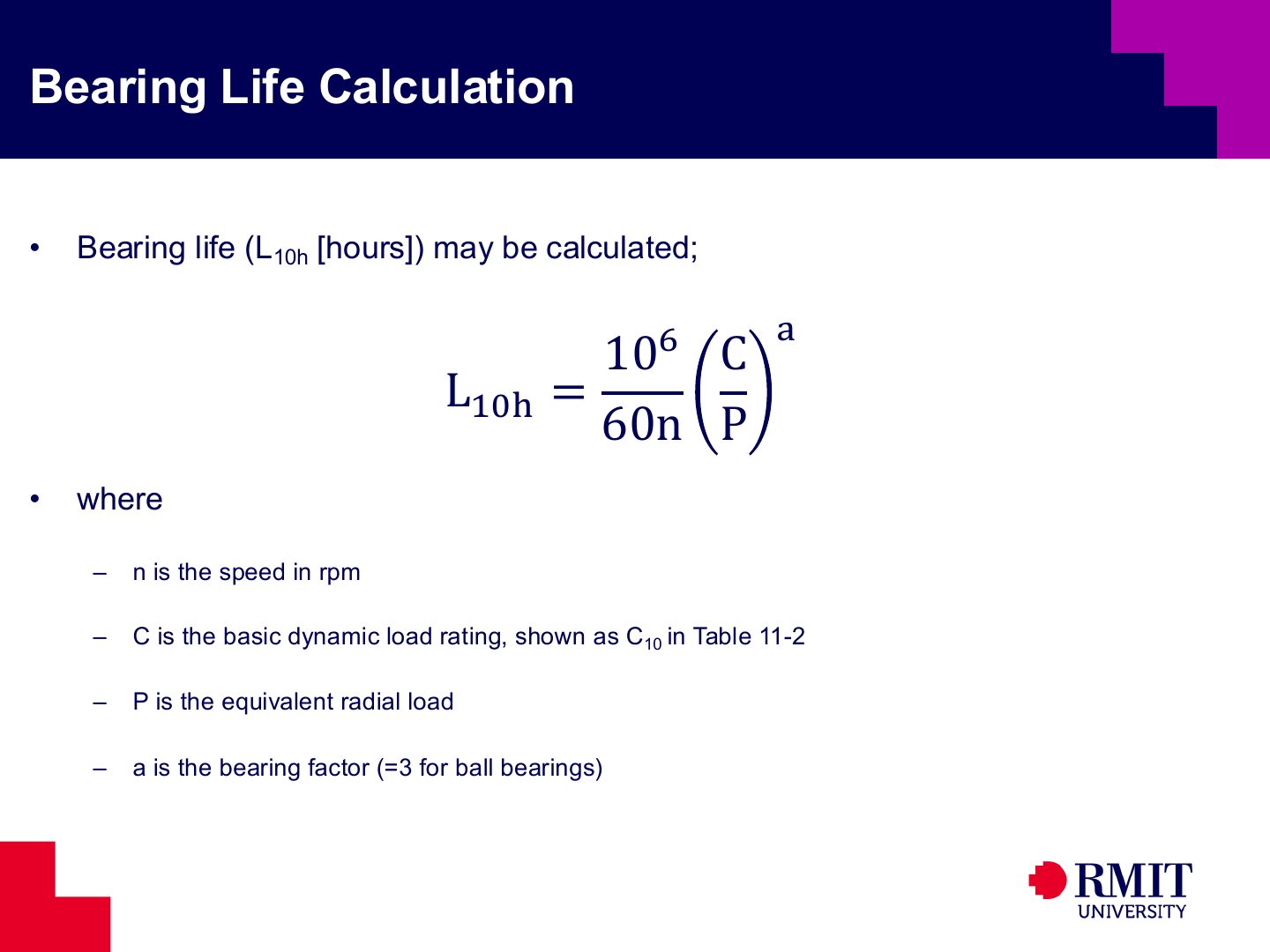
For constant speed and load, basic rating life in hours is
\[L_{10h}=\frac{10^6}{60n}\left(\frac{C}{P}\right)^a.\]Here $n$ is speed in rpm, $C$ is the dynamic load rating, $P$ is the equivalent dynamic load and $a=3$ for a ball bearing. The result has 90% reliability. It is not a guaranteed operating life for one bearing.
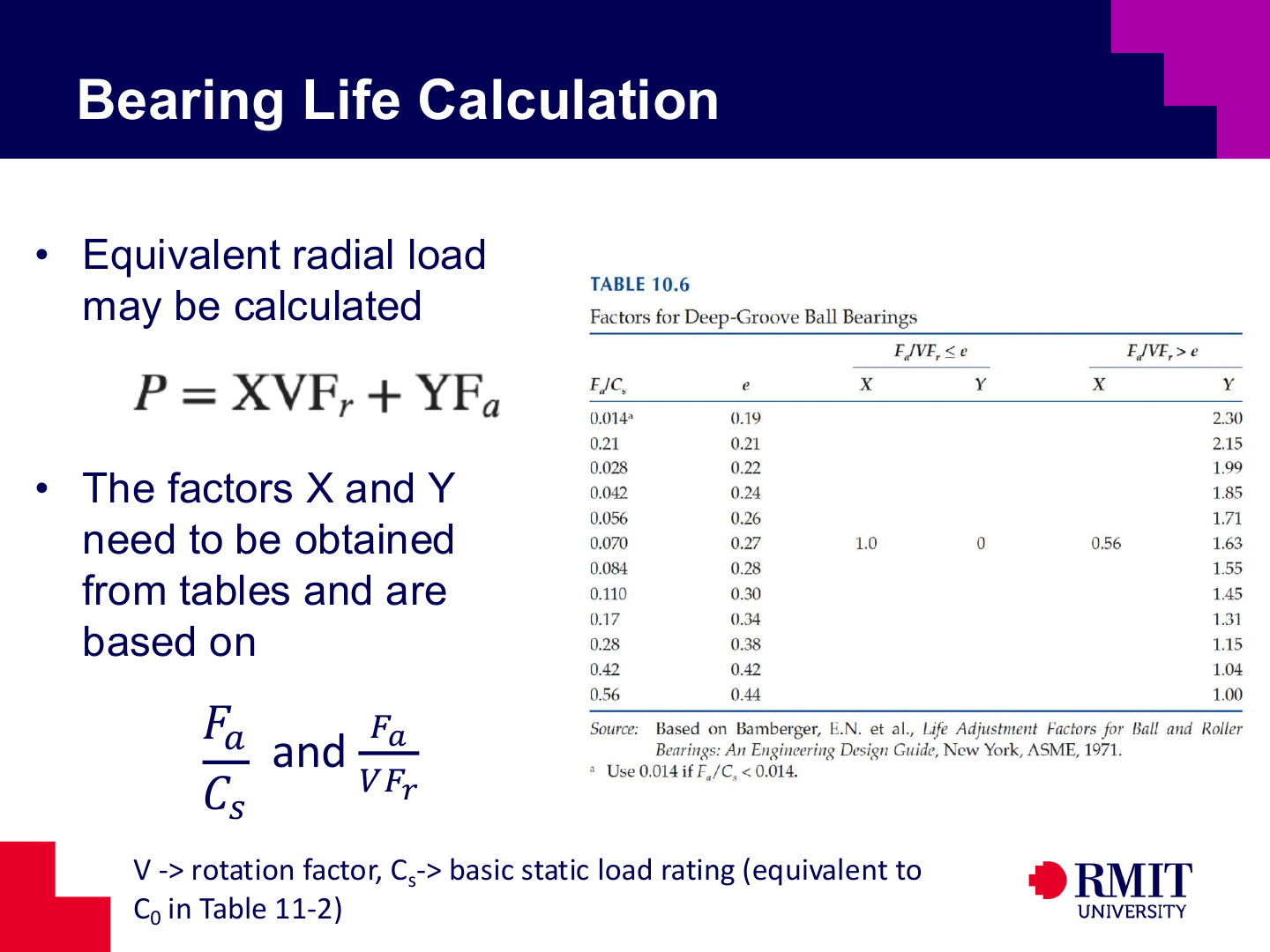
For a deep-groove ball bearing under combined load,
\[P=XVF_r+YF_a.\]The catalogue factors $X$ and $Y$ depend on the ratio of axial load to radial load. They also depend on the limit $e$, which is found from the factor table using $F_a/C_s$. Here, $C_s$ is the basic static load rating and is the same quantity as $C_0$ in Table 11-2. If $F_a/C_s$ falls between two table entries, use linear interpolation to find $e$ and, when needed, $Y$. The rotation factor $V$ depends on which bearing ring rotates relative to the load. Compare $e$ with $F_a/(VF_r)$, not $F_a/F_r$, because the catalogue definition includes $V$.
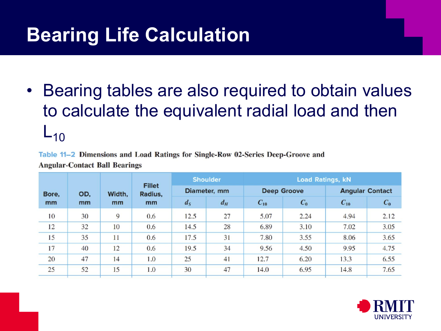
A life calculation needs the bearing dimensions, load ratings and the manufacturer’s combined-load factors. Table 11-2 gives $C_{10}$ and $C_0$; in the equations, use $C=C_{10}$ and $C_s=C_0$. The ratio $F_a/(VF_r)$ determines which values of $X$ and $Y$ to use. Deep-groove and angular-contact bearings with the same bore can have different ratings and factor tables. For an angular-contact bearing, select the factors for its contact angle. Do not use a rating or factor from a different bearing family, even if the bore is the same.
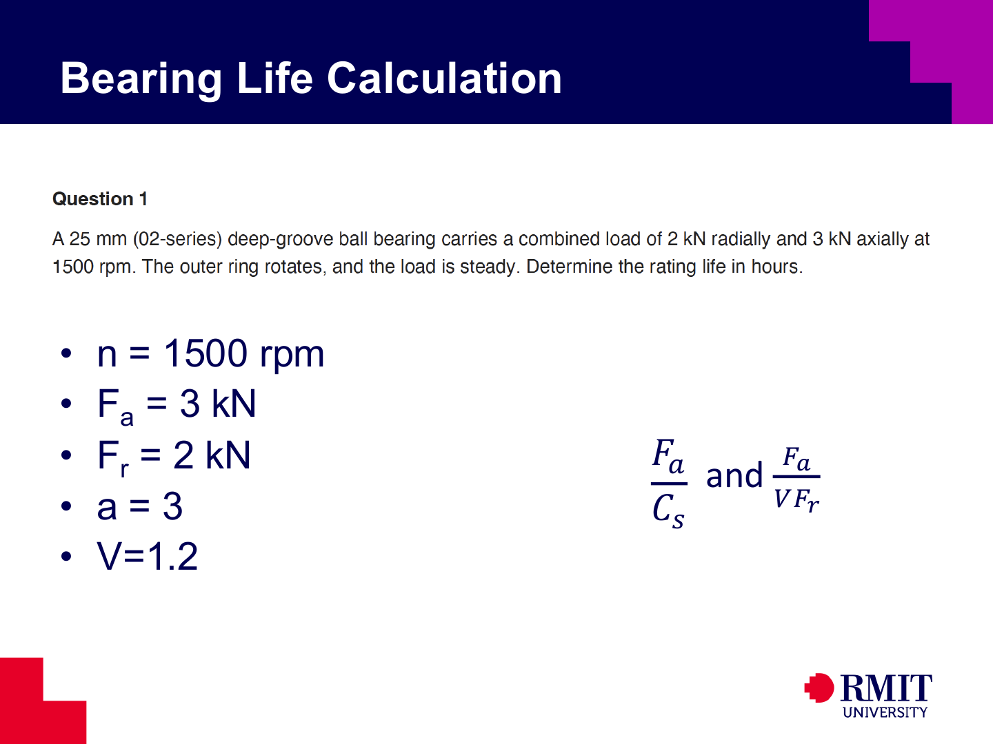
The example uses a 25 mm deep-groove ball bearing operating at $1500\ \text{rpm}$. The loads are $F_r=2\ \text{kN}$ and $F_a=3\ \text{kN}$, with $V=1.2$ and $a=3$. The axial load is large compared with the radial load. The catalogue test must therefore be completed before deciding which load equation to use.
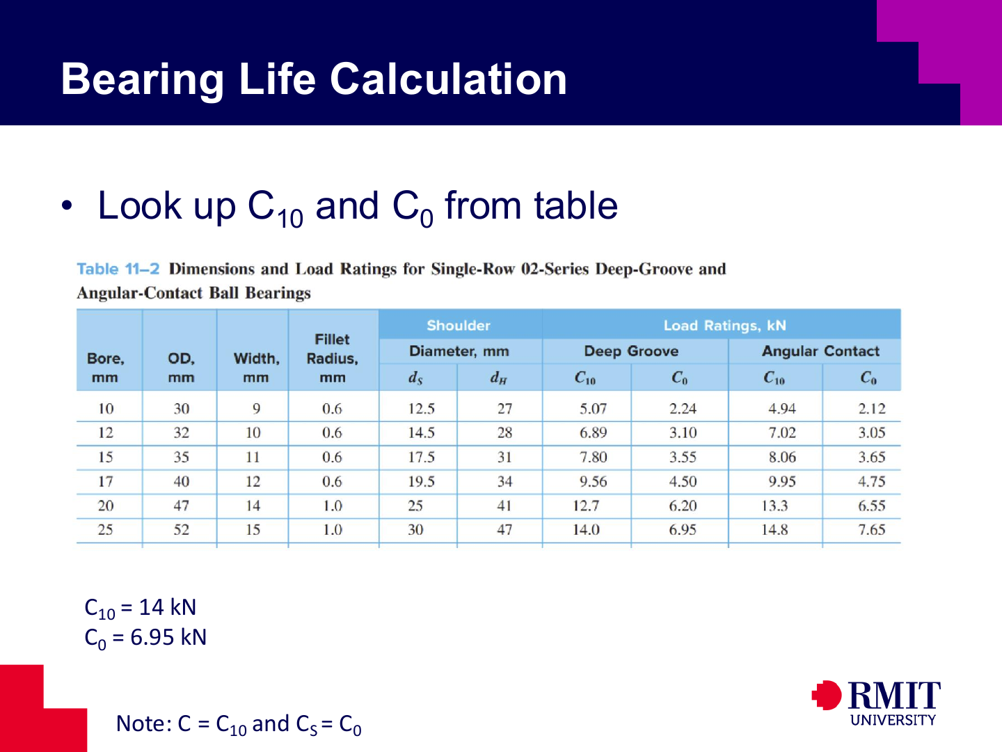
For the selected 25 mm 02-series bearing, Table 11-2 gives $C_{10}=14\ \text{kN}$ and $C_0=6.95\ \text{kN}$. Therefore, use the dynamic rating $C=C_{10}=14\ \text{kN}$ in the fatigue-life equation and the static rating $C_s=C_0=6.95\ \text{kN}$ to select the combined-load factors.
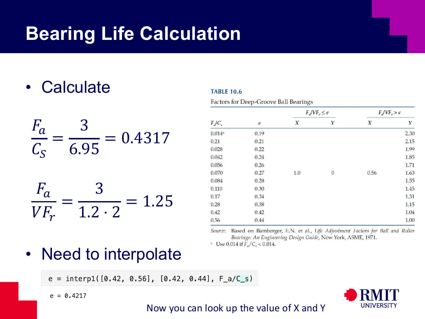
These ratios have no units because all forces use the same unit:
\[\frac{F_a}{C_s}=\frac{F_a}{C_0}=\frac{3}{6.95}=0.4317,\qquad \frac{F_a}{VF_r}=\frac{3}{1.2(2)}=1.25.\]If the required value lies between two entries $x_1$ and $x_2$ in a table, use linear interpolation:
\[y=y_1+\frac{x-x_1}{x_2-x_1}(y_2-y_1).\]Using the two neighbouring $F_a/C_s$ entries gives $e\approx0.4217$. Because $F_a/(VF_r)>e$, use the combined-load equation with $X=0.56$. Use the same interpolation method to find $Y$ from the two neighbouring table entries. Only interpolate between values inside the table. Do not calculate beyond the table limits without more information from the manufacturer.
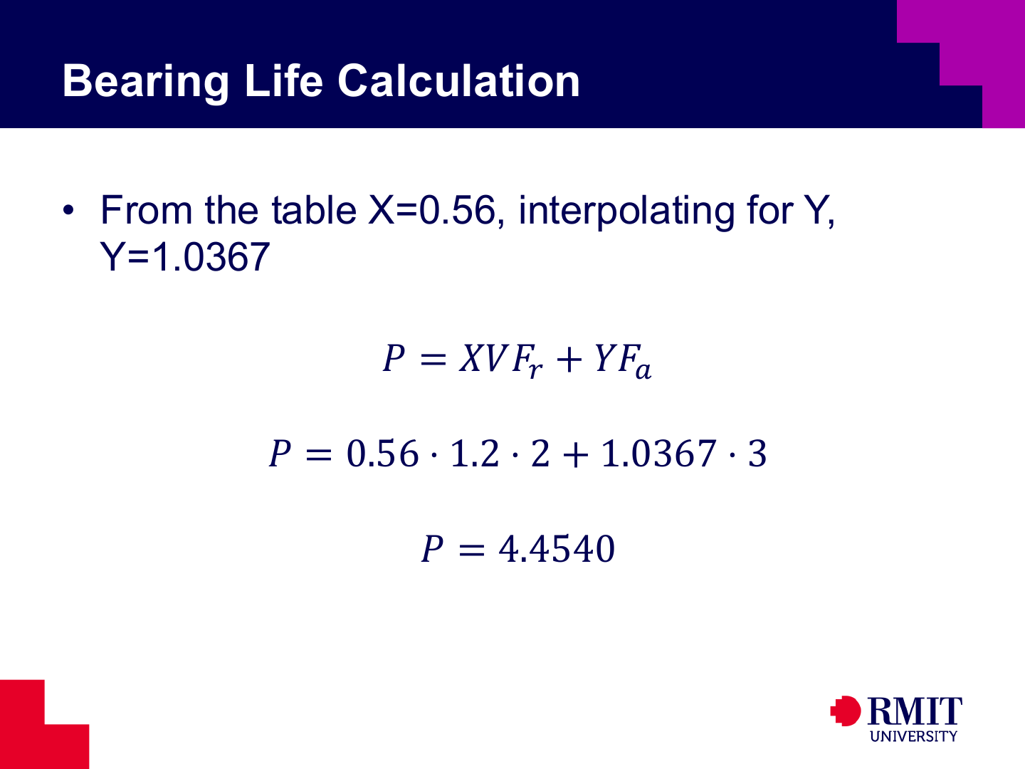
Linear interpolation gives $Y\approx1.0367$. The equivalent radial load is then
\[P=0.56(1.2)(2)+1.0367(3)=4.4541\ \text{kN}\approx4.4540\ \text{kN}.\]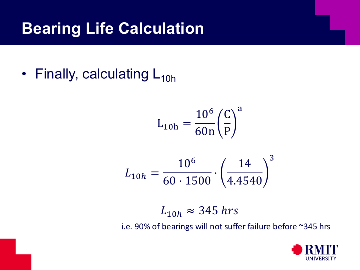
Putting the dynamic rating and equivalent load into the life equation gives
\[L_{10h}=\frac{10^6}{60(1500)}\left(\frac{14}{4.4540}\right)^3 =345.05\ \text{hours}.\]This calculation assumes constant load and constant speed. Under these conditions, 90% of a large group of identical bearings is expected to operate for approximately 345 hours before showing the first signs of rolling-contact fatigue.

Knowledge Check
Use this quiz to check your understanding of bearings, rating life, equivalent load, reliability and lubrication. Check each question separately.
1. What does the basic rating life $L_{10}$ represent?
2. How are the dynamic rating $C$ and static rating $C_0$ used?
3. Which equation should be used when $F_a/(VF_r)>e$ for a radial bearing carrying both radial and axial loads?
4. Which rotation factor applies when the outer ring rotates relative to a stationary load under the stated catalogue convention?
5. Which life exponent is normally used for a cylindrical roller bearing?
6. A ball bearing has $C/P=4$. What is its basic rating life in revolutions?
7. How does a service factor $K_s>1$ affect a bearing-life calculation?
8. What reliability corresponds to a permitted failure probability of 2%?
9. If $L_{10h}=1000$ hours, can the median life be calculated when no life distribution or adjustment factor is given?
10. Two roller bearings have the same bore and operate under the same $P$ and speed. Which one has the longer predicted rating life?
11. Which expression gives the projected pressure for a journal bearing?
12. How is load-supporting pressure generated in a hydrodynamic journal bearing?