Velocity Analysis (Vector Loop Method)
Four-Bar Crank-Slider Vector Loop Equations
The derivation of the vector loop equation for a four-bar crank-slider mechanism follows the same closure logic as the four-bar linkage, except that one end point is constrained to move on a straight guide. In the notation used here, the crank has length $a$, the coupler has length $b$, the slider position is $d$, and $c$ is the signed vertical offset of the slider axis relative to $O_2$. Thus $c<0$ when the slider axis is below $O_2$ and $c>0$ when it is above $O_2$.
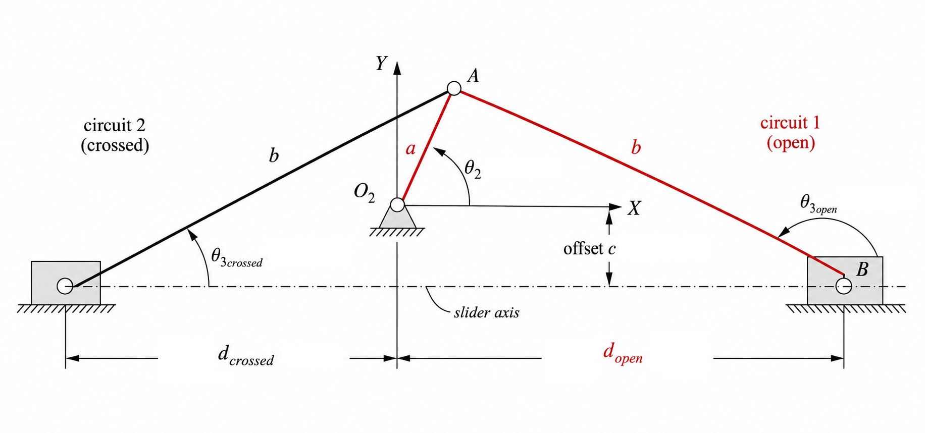
Vector Loop Equation
Traversing the mechanism from the grounded crank pivot to the slider pin gives the closure statement
\[\mathbf{R}_A+\mathbf{R}_{BA}-\mathbf{R}_{BO_2}=0.\]Using complex notation for the rotating links and Cartesian form for the slider position gives
\[a e^{j\theta_2}-b e^{j\theta_3}-(d+jc)=0\]where the slider position vector is $\mathbf{R}_{BO_2}=d+jc$. The offset $c$ is constant for a fixed guide.
Using Euler’s relation, $e^{j\theta}=\cos\theta+j\sin\theta$, this becomes
\[a(\cos\theta_2+j\sin\theta_2)-b(\cos\theta_3+j\sin\theta_3)-(d+jc)=0.\]Solving for Velocities
Determining velocities from the crank-slider vector loop follows the same overall pattern as the conventional four-bar: differentiate the position loop, convert to scalar equations, and solve for the unknown instantaneous rates.
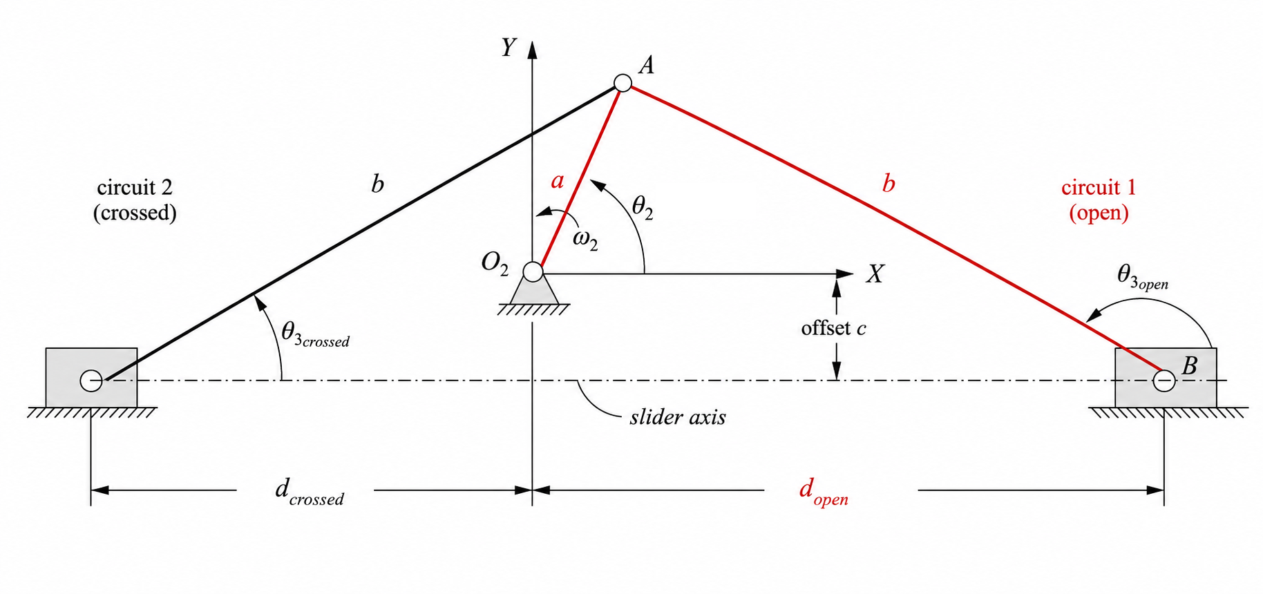
Differentiating the position loop
\[a e^{j\theta_2}-b e^{j\theta_3}-(d+jc)=0\]with respect to time gives
\[j a e^{j\theta_2}\frac{\mathrm{d}\theta_2}{\mathrm{d}t} -j b e^{j\theta_3}\frac{\mathrm{d}\theta_3}{\mathrm{d}t} -\frac{\mathrm{d}d}{\mathrm{d}t}=0.\]Since $c$ is a constant guide offset, its derivative is zero. Using $\frac{\mathrm{d}\theta}{\mathrm{d}t}=\omega$ and $\frac{\mathrm{d}d}{\mathrm{d}t}=\dot d$, the differentiated loop becomes
\[j a \omega_2 e^{j\theta_2}-j b \omega_3 e^{j\theta_3}-\dot d=0.\]The term $\dot d$ is purely real because the slider motion is constrained to remain along the guide axis.
Substitute Euler’s relation and multiply through by $j$ where needed to obtain
\[a\omega_2(-\sin\theta_2+j\cos\theta_2)-b\omega_3(-\sin\theta_3+j\cos\theta_3)-\dot d=0.\]Separating into real and imaginary components gives, first, the real part:
\[-a\omega_2\sin\theta_2+b\omega_3\sin\theta_3-\dot d=0\]and second, the imaginary part:
\[a\omega_2\cos\theta_2-b\omega_3\cos\theta_3=0.\]The imaginary equation contains only the angular quantities, so solve it first:
\[b\omega_3\cos\theta_3=a\omega_2\cos\theta_2\] \[\omega_3=\frac{a\cos\theta_2}{b\cos\theta_3}\omega_2.\]Then substitute $\omega_3$ into the real equation to obtain the slider speed:
\[\dot d=-a\omega_2\sin\theta_2+b\omega_3\sin\theta_3.\]Point Velocities
Once $\omega_3$ is known, the point velocities follow directly from the rigid-body formulas:
\[\mathbf{V}_A=j a \omega_2 e^{j\theta_2} =a\omega_2(-\sin\theta_2+j\cos\theta_2),\] \[\mathbf{V}_{BA}=-j b \omega_3 e^{j\theta_3} =-b\omega_3(-\sin\theta_3+j\cos\theta_3),\] \[\mathbf{V}_B=\dot d\,\hat{\mathbf{i}}.\]The last expression reflects the guide constraint: point $B$ moves only along the slider axis, so its velocity has no imaginary component in this coordinate system.
To determine these velocities, the current value of $\theta_3$ must already be known from the position analysis. Given $\theta_2$ and the mechanism dimensions $a$, $b$, and $c$, that angle can be found using the method discussed in Position Analysis.