Position Analysis (Vector Loop Method)
Four-Bar Crank-Slider Vector Loop Equations
The derivation of the vector loop equation for a four-bar crank-slider mechanism follows the same closure logic as the four-bar linkage, except that one end point is constrained to move on a straight guide. In the notation used here, the crank has length $a$, the coupler has length $b$, the slider position is $d$, and $c$ is the signed vertical offset of the slider axis relative to $O_2$. Thus $c<0$ when the slider axis is below $O_2$ and $c>0$ when it is above $O_2$.
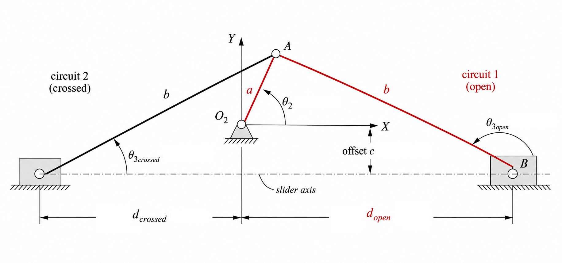
Vector Loop Equation
Traversing the mechanism from the grounded crank pivot to the slider pin gives the closure statement
\[\mathbf{R}_A+\mathbf{R}_{BA}-\mathbf{R}_{BO_2}=0.\]Using complex notation for the rotating links and Cartesian form for the slider position gives
\[a e^{j\theta_2}-b e^{j\theta_3}-(d+jc)=0\]where the slider position vector is $\mathbf{R}_{BO_2}=d+jc$. The offset $c$ is constant for a fixed guide.
Using Euler’s relation, $e^{j\theta}=\cos\theta+j\sin\theta$, this becomes
\[a(\cos\theta_2+j\sin\theta_2)-b(\cos\theta_3+j\sin\theta_3)-(d+jc)=0.\]Solving the Vector Loop Equation
Start from the complex vector-loop equation
\[a e^{j\theta_2}-b e^{j\theta_3}-(d+jc)=0.\]Using Euler’s relation,
\[e^{j\theta}=\cos\theta+j\sin\theta,\]the loop equation becomes
\[a(\cos\theta_2+j\sin\theta_2)-b(\cos\theta_3+j\sin\theta_3)-(d+jc)=0.\]Separating the real and imaginary parts gives
Real part:
\[a\cos\theta_2-b\cos\theta_3-d=0\]Imaginary part:
\[a\sin\theta_2-b\sin\theta_3-c=0.\]Unlike the conventional four-bar, this mechanism has one angular unknown, $\theta_3$, and one linear unknown, $d$. The imaginary equation is therefore the natural place to begin because it contains only $\theta_3$.
Derivation for $\theta_3$
Rearrange the imaginary equation:
\[a\sin\theta_2-b\sin\theta_3-c=0\] \[b\sin\theta_3=a\sin\theta_2-c\] \[\sin\theta_3=\frac{a\sin\theta_2-c}{b}.\]This gives an immediate feasibility check. If
\[\left|\frac{a\sin\theta_2-c}{b}\right|>1,\]then no real value of $\theta_3$ exists and the mechanism cannot close for that chosen input angle.
If the ratio lies between $-1$ and $1$, then two real angular branches are available:
\[\theta_{3,1}=\sin^{-1}\left(\frac{a\sin\theta_2-c}{b}\right),\] \[\theta_{3,2}=180^\circ-\theta_{3,1}.\]These correspond to the two possible assembly modes of the mechanism. In practical calculations, the physically relevant branch is chosen by checking which one produces the expected slider position and configuration.
Derivation for $d$
Once $\theta_3$ is known, substitute the chosen branch into the real equation:
\[a\cos\theta_2-b\cos\theta_3-d=0.\]Rearranging gives
\[d=a\cos\theta_2-b\cos\theta_3.\]This provides the slider position corresponding to the selected angular branch.
Interpretation of the Branches
The two values of $\theta_3$ do not by themselves decide which configuration is physically relevant. After each candidate angle is found, the corresponding value of $d$ must also be evaluated.
If one branch gives a slider position that is inconsistent with the chosen sign convention or the intended assembly mode, that branch is rejected. In this way, the mechanism geometry and the sign convention work together to select the physically meaningful solution.
Summary
For the four-bar crank-slider, the vector-loop position analysis reduces to the pair of direct relations
\[\sin\theta_3=\frac{a\sin\theta_2-c}{b},\] \[d=a\cos\theta_2-b\cos\theta_3.\]This is simpler than the conventional four-bar case because only one rotating unknown remains after the guide constraint has been imposed.