Four-Bar Crank-Slider Mechanism Vector Loop Equations
Four-Bar Crank-Slider Vector Loop Equations
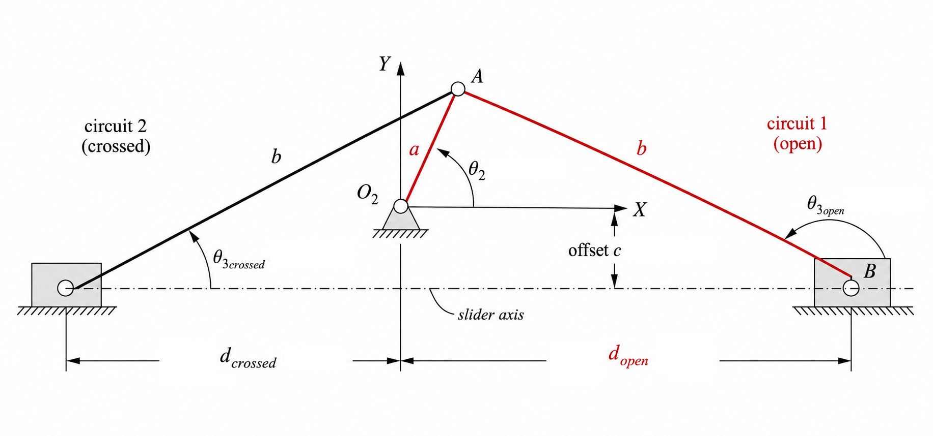
The derivation of the vector loop equation for a four-bar crank-slider mechanism follows the same closure logic as the four-bar linkage, except that one end point is constrained to move on a straight guide. In the notation used here, the crank has length $a$, the coupler has length $b$, the slider position is $d$, and $c$ is the signed vertical offset of the slider axis relative to $O_2$. Thus $c<0$ when the slider axis is below $O_2$ and $c>0$ when it is above $O_2$.
Vector Loop Equation
Traversing the mechanism from the grounded crank pivot to the slider pin gives the closure statement
\[\mathbf{R}_A+\mathbf{R}_{BA}-\mathbf{R}_{BO_2}=0.\]Using complex notation for the rotating links and Cartesian form for the slider position gives
\[a e^{j\theta_2}-b e^{j\theta_3}-(d+jc)=0\]where the slider position vector is $\mathbf{R}_{BO_2}=d+jc$. The offset $c$ is constant for a fixed guide.
Using Euler’s relation, $e^{j\theta}=\cos\theta+j\sin\theta$, this becomes
\[a(\cos\theta_2+j\sin\theta_2)-b(\cos\theta_3+j\sin\theta_3)-(d+jc)=0.\]